Mitsubishi Montero Sport (2004+). Manual - part 773


  Index      Mitsubishi     Mitsubishi Montero Sport - service repair manual 2004 year


Search            


Content   ..  771  772  773  774   ..


Mitsubishi Montero Sport (2004+). Manual - part 773


ON-VEHICLE SERVICE

TSB Revision

BASIC BRAKE SYSTEM

35A-17

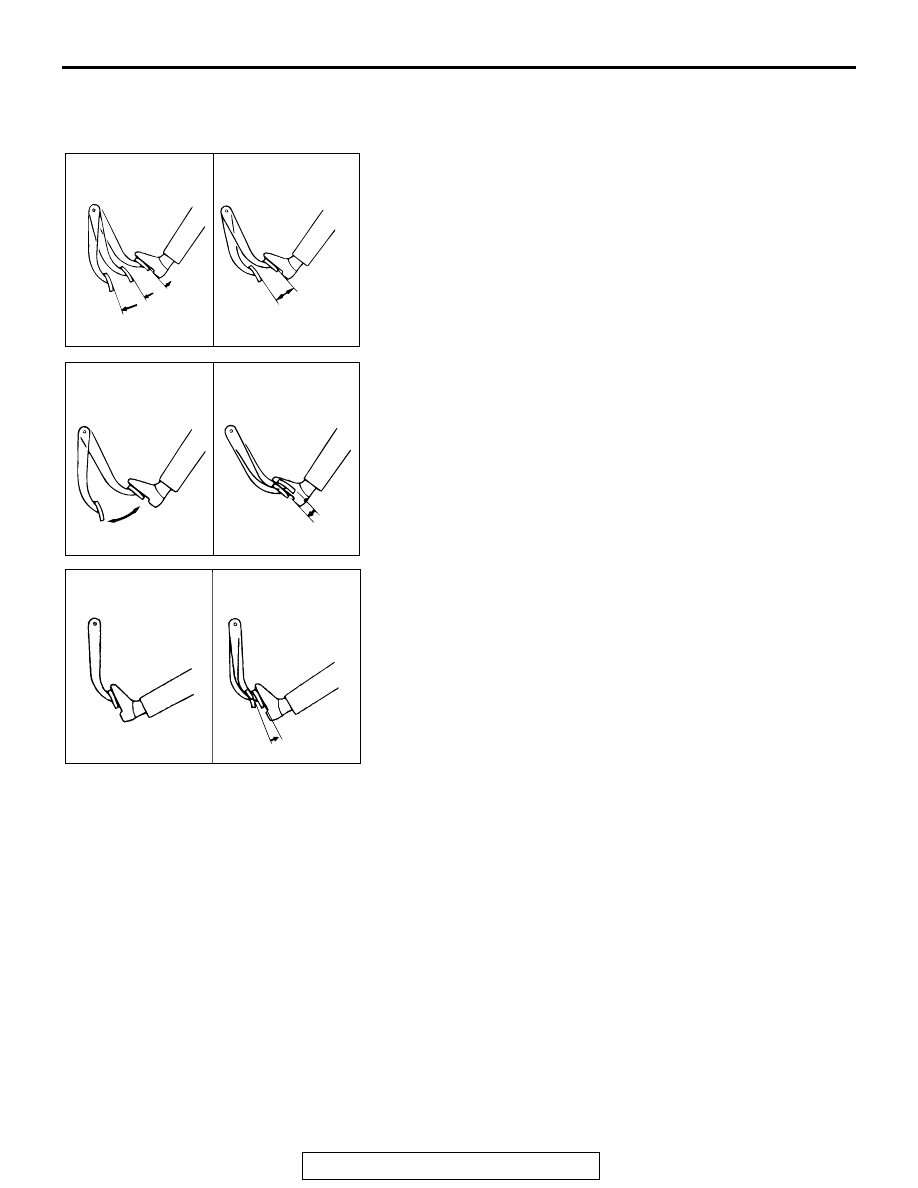
BRAKE BOOSTER OPERATING CHECK

M1351001000394

For simple checking of the brake booster operation, carry out 
the following tests:
1. Run the engine for one or two minutes, and then stop it. If 

the pedal depresses fully the first time but gradually 
becomes higher when depressed succeeding times, the 
booster is operating properly. If the pedal height remains 
unchanged, the booster is defective. Go to step 2.

2. With the engine stopped, step on the brake pedal several 

times. Then step on the brake pedal and start the engine.
If the pedal moves downward slightly, the booster is in good 
condition.
If there is no change, the booster is defective. Go to step 3.

3. With the engine running, step on the brake pedal and then 

stop the engine. Hold the pedal depressed for 30 seconds.
If the pedal height does not change, the booster is in good 
condition, if the pedal rises, the booster is defective. If the 
above three tests are okay, the booster is OK. If one of the 
above three tests is not okay, the check valve, vacuum 
hose, or booster will be defective.
Check the check valve (Refer to 

P.35A-18

.), vacuum hose 

for leaks, high volume engine vacuum applied to booster. 
Repair or replace as necessary. If OK, replace booster and 
this step starting at Step 1.

AC004303 AB

GOOD

NO GOOD

AC004304 AB

WHEN ENGINE
IS STOPPED

WHEN ENGINE
IS STARTED

AC004305 AB

GOOD

NO GOOD

ON-VEHICLE SERVICE

TSB Revision

BASIC BRAKE SYSTEM

35A-18

CHECK VALVE OPERATION CHECK

M1351009000398

CAUTION

The check valve should not be removed from the vacuum 
hose.
1. Remove the vacuum hose. (Refer to 

P.35A-28

.)

CAUTION

If the check valve is defective, replace it as an assembly 
unit together with the vacuum hose.
2. Check the operation of the check valve by using a vacuum 

pump.

PROPORTIONING VALVE FUNCTION TEST 
<VEHICLES WITHOUT ABS>

M1351001100379

1. Connect two pressure gauges, one each to the input side 

and output side of the proportioning valve, as shown.

2. Bleed the air in the brake line and the pressure gauge.
3. While gradually depressing the brake pedal, make the 

following measurements and check to be sure that the 
measured values are within the allowable range.

(1) Output pressure begins to drop relative to input pressure 

(split point).

Standard value:

VACUUM PUMP 
CONNECTION

CRITERIA

Connection at the brake 
booster side (A)

A negative pressure 
(vacuum) is created and 
held.

Connection at the intake 
manifold side (B)

A negative pressure 
(vacuum) is not created.

AC004325 AB

VALVE

SPRING

BOOSTER
SIDE
(HOLDS)

INTAKE
MANIFOLD
SIDE
(DOES NOT
HOLDS)

Vehicles with 15 inch front 
disc brake disc

2,452 kPa (356 psi)

Vehicles with 16 inch front 
disc brake disc

3,432 kPa (498 psi)

AC004334 AB

PROPORTIONING
VALVE

PRESSURE
GAUGE

AC004334 AB

PROPORTIONING
VALVE

PRESSURE
GAUGE

ON-VEHICLE SERVICE

TSB Revision

BASIC BRAKE SYSTEM

35A-19

(2) Check to be sure that the output fluid pressure is at the 

standard value when the pedal depression force is 
increased so that the input fluid pressure is at the values 
shown in the table below.

Standard value:

BLEEDING

M1351001400488

CAUTION

Use only the specified brake fluid. Never mix the specified 
brake fluid with other fluid as it will influence the braking 
performance significantly.

Specified brake fluid: DOT3 or DOT4

.

MASTER CYLINDER BLEEDING
The master cylinder used has no check valve, so if bleeding is 
carried out by the following procedure, bleeding of air from the 
brake pipeline will become easier. (When brake fluid is not con-
tained in the master cylinder.)
1. Fill the reserve tank with brake fluid.
2. Keep the brake pedal depressed.
3. Have another person cover the master cylinder outlet with a 

finger.

4. With the outlet still closed, release the brake pedal.
5. Repeat steps (2) 

− (4) three or four times to fill the inside of 

the master cylinder with brake fluid.

.

BRAKE LINE BLEEDING
Start the engine and bleed the air in the sequence shown in the 
figure.

Input fluid pressure kPa (psi)

5,884 (853)

Output fluid 
pressure kPa (psi)

Vehicles with 15 
inch front disc 
brake disc

3,526 

− 3,918 

(512 

− 568)

Vehicles with 16 
inch front disc 
brake disc

4,114 

− 4,536 

(601 

− 657)

AC004348 AB

AC004349

1

2

3

4

AB

ON-VEHICLE SERVICE

TSB Revision

BASIC BRAKE SYSTEM

35A-20

BRAKE FLUID LEVEL SWITCH CHECK

M1351009100425

The brake fluid level switch is in good condition if there is no 
continuity when the float surface is above "A" and if there is 
continuity when the float surface is below "A."

DISC BRAKE PAD CHECK AND REPLACEMENT

M1351002300451

NOTE: The brake pads have indicators that contact the brake 
disc when the brake pad thickness becomes 2 mm (0.08 inch), 
and emit a squealing sound to warn the driver.

CAUTION

• Whenever a pad must be replaced, replace both LH and 

RH wheel pads as a set to prevent the vehicle from pull-
ing to one side when braking.

• If there is a significant difference in the thicknesses of 

the pads on the left and right sides, check the sliding 
condition of the piston, lock pin and guide pin.

1. Check the brake pad thickness through the caliper body 

check port.

Standard value: 10.0 mm (0.39 inch)
Minimum limit: 2.0 mm (0.08 inch)

CAUTION

Do not wipe the special grease from the lock pin. Do not 
contaminate the lock pin.
2. Remove the lock pin. Lift the caliper assembly and secure it 

with a wire.

AC004358 AB

A

AC004362

WEAR INDICATOR

BRAKE
DISC

PAD

WHEN NEW

WHEN WORN

AB

AC004363

AC203823 AB


Content   ..  771  772  773  774   ..