Mitsubishi Montero Sport (2004+). Manual - part 772


  Index      Mitsubishi     Mitsubishi Montero Sport - service repair manual 2004 year


Search            


Content   ..  770  771  772  773   ..


Mitsubishi Montero Sport (2004+). Manual - part 772


BASIC BRAKE SYSTEM DIAGNOSIS

TSB Revision

BASIC BRAKE SYSTEM

35A-13

STEP 8. Check whether the brake booster, master cylinder 
or wheel cylinder return is insufficient.
Q: Is the brake booster, master cylinder or wheel cylinder 

return insufficient?
YES : 
Replace the part. Then go to Step 10.
NO :  Go to Step 9.

STEP 9. Adjust the brake pedal or brake booster pushrod.

Refer to 

P.35A-15

 or 

P.35A-28

.

Q: Is the adjustment value come?

YES : Adjust. Then go to Step 10.
NO :  Go to Step 10.

STEP 10. Retest the system.
Q: Is the symptom eliminated?

YES : The procedure is complete.
NO :  Start over at Step 1. If a new symptom surfaces, refer 

to the symptom chart 

P.35A-3

.

INSPECTION PROCEDURE 9: Groaning, Clicking or Rattling Noise when Brakes are not Applied.

.

DIAGNOSIS

STEP 1. Check whether foreign material has entered the 
wheel covers.
Q: Is there foreign material?

YES : Remove it. Then go to Step 5.
NO :  Go to Step 2.

STEP 2. Check for looseness of the wheel nuts.
Q: Are the wheel nuts loose?

YES : Tighten to 98 

− 120 N⋅m (72 − 87 ft-lb). Then go to 

Step 5.

NO :  Go to Step 3.

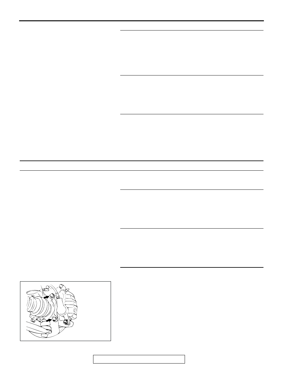
STEP 3. Check for looseness of the caliper installation 
bolt.

Q: Is the caliper installation bolt loose?

YES : Tighten to 88 N

⋅m (65 ft-lb). Then go to Step 5.

NO :  Go to Step 4.

AC000863

AB

SPECIAL TOOLS

TSB Revision

BASIC BRAKE SYSTEM

35A-14

STEP 4. Check the wheel bearings for wear, damage or 
dryness.

Q: Is there fault?

YES : Apply grease or replace the part. Then go to Step 5.
NO :  Go to Step 5.

STEP 5. Retest the system.
Q: Is the symptom eliminated?

YES : The procedure is complete.
NO :  Start over at Step 1. If a new symptom surfaces, refer 

to the symptom chart 

P.35A-3

.

SPECIAL TOOLS

M1351000600393

AC005073 AB

<FRONT>

<REAR>

WHEEL BEARING

WHEEL
BEARING

TOOL

TOOL NUMBER AND 
NAME

SUPERSESSION

APPLICATION

MB990964
Brake tool set
A: MB990520
Disc brake piston expander
B: MB990623
Installer

General service 
tool

• Pushing-in of the disc brake 

piston

• Installation of the drum brake 

wheel cylinder piston cup

MB991714
Pushrod adjust gauge

Clearance adjustment between 
brake booster pushrod and 
master cylinder primary piston

MB990964

A

B

B

MB991714

ON-VEHICLE SERVICE

TSB Revision

BASIC BRAKE SYSTEM

35A-15

ON-VEHICLE SERVICE

BRAKE PEDAL CHECK AND ADJUSTMENT

M1351000900468

.

BRAKE PEDAL HEIGHT
1. Turn up the carpet etc. under the brake pedal.
2. Measure the brake pedal height as illustrated. If it is not 

within the standard value, adjust as follows.

Standard value: 176 

 181 mm (6.9  7.1 inches) [From 

the surface of melting sheet (floorboard) to the face of 
pedal pad]

(1) Disconnect the stoplight switch connector, loosen the jam 

nut and move the stoplight switch to a position where it 
does not contact the brake pedal arm.

(2) Adjust the brake pedal height by turning the operating rod 

with pliers (with the operating rod jam nut loosened).

(3) Screw in the stoplight switch until it contacts the brake 

pedal stopper (just before brake pedal begins to move). 
Return the stoplight switch half to one turn and secure 
with the jam nut.

(4) Connect the connector of the stoplight switch.
(5) Check to be sure that the stoplight is not illuminated with 

the brake pedal released.

3. Turn back the carpet etc. to original position.

.

AC005033 AB

OPERAT-
ING ROD

OPERATING
ROD JAM
NUT

STOPLIGHT
SWITCH

STOPLIGHT
SWITCH
JAM NUT

ACX01815AB

JAM NUT

PEDAL UP

PEDAL 
DOWN

AC005034 AB

0.5 - 1.0 mm
(0.02 - 0.04 in)

OUTER CASE

JAM NUT

ON-VEHICLE SERVICE

TSB Revision

BASIC BRAKE SYSTEM

35A-16

BRAKE PEDAL FREE PLAY
1. Turn the ignition switch to the "LOCK" (OFF) position, 

depress the brake pedal two or three times. After eliminating 
the vacuum in the brake booster, press the pedal down by 
hand, and confirm that the amount of movement before 
resistance is met (free play) is within the standard value 
range.

Standard value: 3 

 8 mm (0.1  0.3 inch)

2. If the free play exceeds the standard value, it is probably 

due to excessive play between the clevis pin and brake 
pedal arm.

3. Check for excessive clearance and replace faulty parts as 

required. (Refer to 

P.35A-27

.)

.

CLEARANCE BETWEEN BRAKE PEDAL AND 
FLOORBOARD
1. Turn up the carpet etc. under the brake pedal.
2. Start the engine, depress the brake pedal with 

approximately 490 N (110 pound) of force, and measure the 
clearance between the brake pedal and the floorboard.

Standard value: 95 mm (3.7 inches) or more [From the 
surface of melting sheet (floorboard) to the face of 
pedal pad]

3. If the clearance is outside the standard value, check for air 

trapped in the brake line, clearance between the lining, and 
the drum and dragging in the parking brake. Adjust and 
replace defective parts as required.

4. Return the carpet etc. to its original position.

STOPLIGHT SWITCH CHECK

M1351008900257

Connect an ohmmeter to the stoplight switch, and Check for 
continuity by pushing in and releasing the stoplight switch. The 
stoplight switch is in good condition if there is no continuity 
when the plunger is pushed in to a depth of within 4 mm (0.2 
inch) from the outer case edge surface, and if there is continu-
ity when it is released.
Check for continuity between the terminals "a" and "b" of the 
stoplight switch.

AC005035 AB

AC005036AB

AC004299 AC

NO CONTINUITY

CONTINUITY

PLUNGER

a

b


Content   ..  770  771  772  773   ..