Mitsubishi Montero Sport (2004+). Manual - part 747


  Index      Mitsubishi     Mitsubishi Montero Sport - service repair manual 2004 year


Search            


Content   ..  745  746  747  748   ..


Mitsubishi Montero Sport (2004+). Manual - part 747


SRS AIR BAG DIAGNOSIS

TSB Revision

SUPPLEMENTAL RESTRAINT SYSTEM (SRS)

52B-57

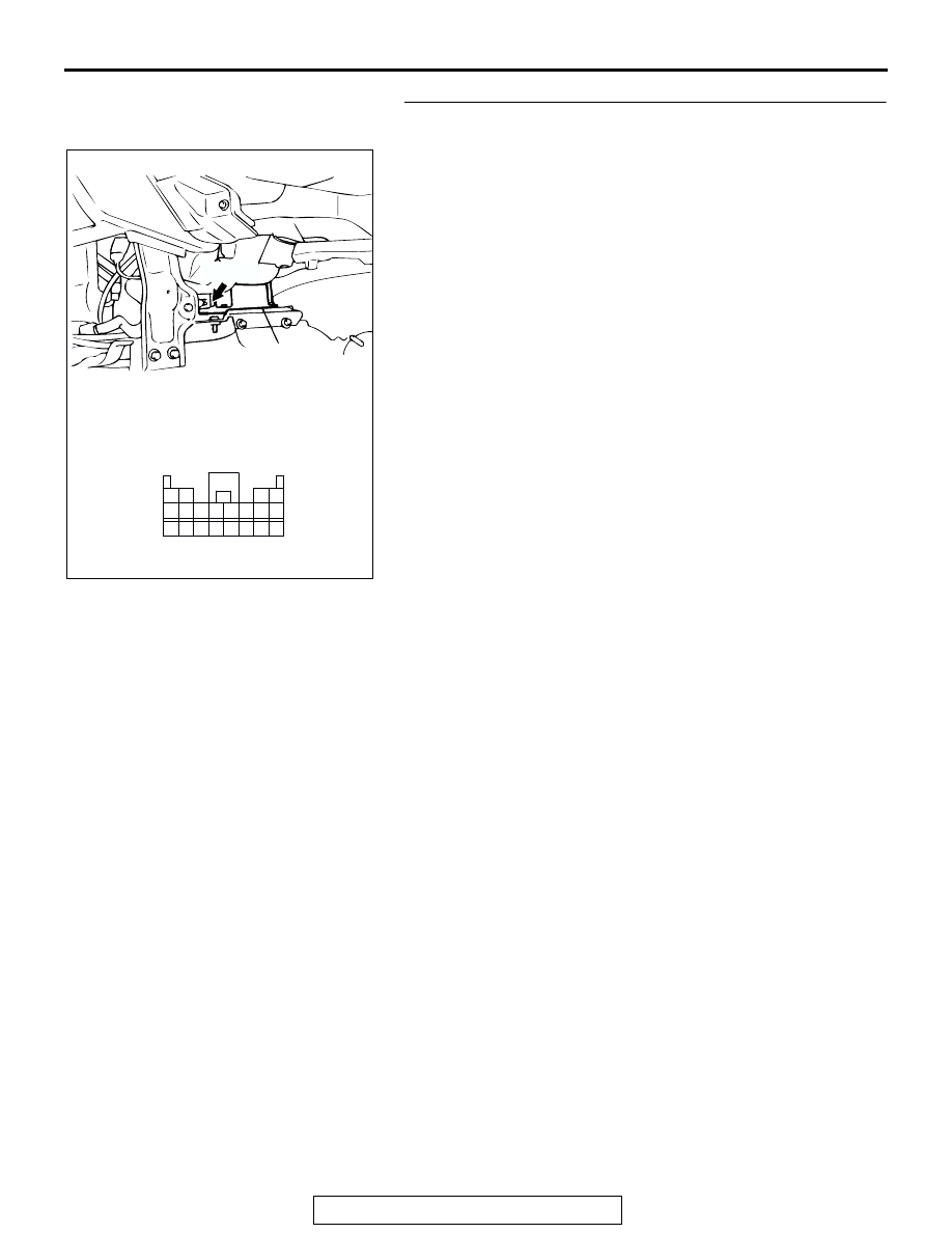
STEP 3. Check the harness wires between ignition switch 
(IG

1

) and SRS-ECU connector C-24 (terminal No. 8).

AC202743

20

19

18

17

7

15

8

16

6

5

4

12

13 14

3

2

1

9 10 11

CONNECTOR: C-24

C-24 (Y)

C-24 HARNESS CONNECTOR:
HARNESS SIDE 
(REAR VIEW) 

AD

SRS-ECU

SRS AIR BAG DIAGNOSIS

TSB Revision

SUPPLEMENTAL RESTRAINT SYSTEM (SRS)

52B-58

NOTE: After inspecting intermediate connectors C-02, C-04, 
D-06, D-08 inspect the wiring harness.
If intermediate connectors C-02, C-04, D-06, D-08 are dam-
aged, repair or replace them. Refer to GROUP 00E, Harness 
Connector Inspection 

P.00E-2

.

Then go to Step 6.
Q: Are the harness wires between ignition switch (IG

1

) and 

SRS-ECU connector C-24 (terminal No.8) in good 
condition?
YES : 
Go to Step 4.
NO :   Repair or replace the harness wire. Then go to Step 

6.

AC200760 

51

52

53

54

55

56

57

58

59

60

61

62

31

32

3029

27

28

2625

2322

24

21

CONNECTORS: C-02, C-04

C-02 (B)

C-04

C-02 HARNESS CONNECTOR:
COMPONENT SIDE

C-04 HARNESS CONNECTOR:
COMPONENT SIDE 

AB

AC200761

1
8

3

4

5

7 6

14

14

15

13

11

12

10

9

2

CONNECTOR D-06

D-06 HARNESS CONNECTOR:
COMPONENT SIDE

AB

JUNCTION BLOCK
(FRONT)

D-06

AC200765

3

4

1

2

CONNECTOR: D-08

D-08 HARNESS CONNECTOR:
COMPONENT SIDE

AB

JUNCTION BLOCK (REAR)

D-05

SRS AIR BAG DIAGNOSIS

TSB Revision

SUPPLEMENTAL RESTRAINT SYSTEM (SRS)

52B-59

STEP 4. Check the ground line at SRS-ECU connector 
C-24.

(1) Disconnect SRS-ECU connector C-24 and measure at the 

harness side (rear side).

(2) Measure the resistance between terminal 7 and ground.

• It should be less than 2 ohms.

Q: Does continuity exist?

YES : Go to Step 6.
NO :  Go to Step 5.

AC202743

20

19

18

17

7

15

8

16

6

5

4

12

13 14

3

2

1

9 10 11

CONNECTOR: C-24

C-24 (Y)

C-24 HARNESS CONNECTOR:
HARNESS SIDE 
(REAR VIEW) 

AD

SRS-ECU

AC003298

<MEASURING METHOD: SAMPLE>

MB991222

AD

C-24 HARNESS CONNECTOR:
HARNESS SIDE

SRS AIR BAG DIAGNOSIS

TSB Revision

SUPPLEMENTAL RESTRAINT SYSTEM (SRS)

52B-60

STEP 5. Check the harness wires between SRS-ECU 
connector C-24 (terminal No.7) and ground.

NOTE: After inspecting he intermediate connector D-13, 
inspect the wiring harness.
If intermediate connector D-13 is damaged, repair or replace it. 
Refer to GROUP 00E, Harness Connector Inspection 

P.00E-2

.

Then go to Step 6.
Q: Are the harness wires between SRS-ECU connector 

C-24 (terminal No.7) and ground in good condition?
YES : 
Go to Step 6.
NO :  Repair or replace the harness wire. Then go to Step 6.

STEP 6.Recheck for diagnostic trouble code.
Q: Is any of DTC 43 or 44 set?

YES : There is no action to be taken.
NO :  The procedure is complete.(If no malfunctions are 

found in all steps, an intermittent malfunction is 
suspected. Refer to GROUP 00, How to Use 
Troubleshooting/Inspection Service Points 

− How to 

Cope with Intermittent Malfunction 

P.00-7

AC202743

20

19

18

17

7

15

8

16

6

5

4

12

13 14

3

2

1

9 10 11

CONNECTOR: C-24

C-24 (Y)

C-24 HARNESS CONNECTOR:
HARNESS SIDE 
(REAR VIEW) 

AD

SRS-ECU

AC202747

1

10

2

11

3

12

4

13

14

15

5

16

6

17

7

18

8

19

9

20

D-13 HARNESS CONNECTOR:
COMPONENT SIDE

CONNECTOR: D-13

D-13

AB


Content   ..  745  746  747  748   ..