Mitsubishi Montero Sport (2004+). Manual - part 745


  Index      Mitsubishi     Mitsubishi Montero Sport - service repair manual 2004 year


Search            


Content   ..  743  744  745  746   ..


Mitsubishi Montero Sport (2004+). Manual - part 745


SRS AIR BAG DIAGNOSIS

TSB Revision

SUPPLEMENTAL RESTRAINT SYSTEM (SRS)

52B-49

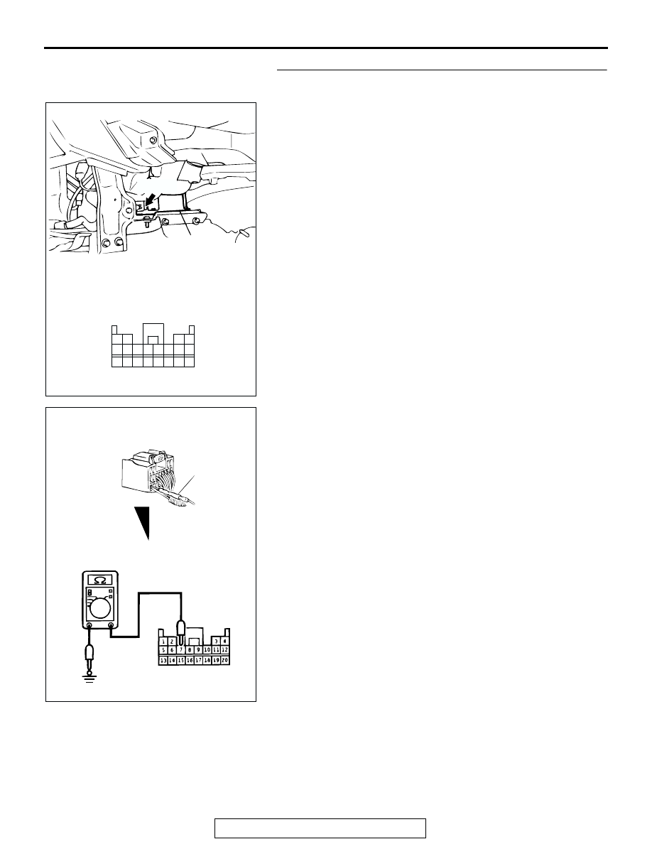
STEP 1. Check the ground line at SRS-ECU connector 
C-24.

(1) Disconnect SRS-ECU connector C-24 and measure at the 

harness side (rear side).

(2) Measure the resistance between terminal 7 and ground.

• It should be less than 2 ohms.

Q: Does continuity exist ?

YES : Go to Step 3.
NO :  Go to Step 2.

AC202743

20

19

18

17

7

15

8

16

6

5

4

12

13 14

3

2

1

9 10 11

CONNECTOR: C-24

C-24 (Y)

C-24 HARNESS CONNECTOR:
HARNESS SIDE 
(REAR VIEW) 

AD

SRS-ECU

AC003298

<MEASURING METHOD: SAMPLE>

MB991222

AC

C-24 HARNESS CONNECTOR:
HARNESS SIDE 

SRS AIR BAG DIAGNOSIS

TSB Revision

SUPPLEMENTAL RESTRAINT SYSTEM (SRS)

52B-50

STEP 2. Check the harness wires between SRS-ECU 
connector C-24 (terminal No.7) and ground.

NOTE: After inspecting intermediate connectors D-13, inspect 
the wiring harness.
If intermediate connector D-13 is damaged, repair or replace it. 
Refer to GROUP 00E, Harness Connector Inspection 

P.00E-2

Go to Step 5.
Q: Are harness wires between the SRS-ECU connector 

C-24 (terminal No.7) and the ground in good condition?
YES : 
Go to Step 5.
NO :  Repair them. Then go to Step 5.

AC202743

20

19

18

17

7

15

8

16

6

5

4

12

13 14

3

2

1

9 10 11

CONNECTOR: C-24

C-24 (Y)

C-24 HARNESS CONNECTOR:
HARNESS SIDE 
(REAR VIEW) 

AD

SRS-ECU

AC003299AH

D-13

JUNCTION BLOCK
(REAR)

1

2

3

4

5

6

7

8

9

10

11

12

13

14

15

16

17

18

19

20

D-13 HARNESS 
CONNECTOR:
COMPONENT SIDE

CONNECTOR: D-13

SRS AIR BAG DIAGNOSIS

TSB Revision

SUPPLEMENTAL RESTRAINT SYSTEM (SRS)

52B-51

STEP 3. Measure the ignition switch (IG

1

) line voltage at 

SRS-ECU connector C-24.

(1) Disconnect SRS-ECU connector C-24 and measure at the 

harness side (rear side).

(2) Turn the ignition switch to the "ON position."

(3) Measure the voltage between terminal 13 (for DTC 42) or 

16(for DTC 41) and the ground.

• Voltage should measure 9 volts or more

Q: Is the voltage 9 volts or more?

YES : Replace the SRS-ECU. Refer to 

P.52B-82

. Then go 

to Step 5.

NO :  Go to Step 4.

AC202743

20

19

18

17

7

15

8

16

6

5

4

12

13 14

3

2

1

9 10 11

CONNECTOR: C-24

C-24 (Y)

C-24 HARNESS CONNECTOR:
HARNESS SIDE 
(REAR VIEW) 

AD

SRS-ECU

AC003300

SRS-ECU HARNESS
CONNECTOR: C-24

MB991222

AC

C-24 HARNESS CONNECTOR:
HARNESS SIDE

SRS AIR BAG DIAGNOSIS

TSB Revision

SUPPLEMENTAL RESTRAINT SYSTEM (SRS)

52B-52

STEP 4. Check the harness wires between the ignition 
switch (IG

1

) and SRS-ECU connector C-24 (terminal No.13 

and 16).

NOTE: After inspecting intermediate connector D-08, or D-13 
(for DTC 42) or D-14 (for DTC 41) inspect the wiring harness. If 
intermediate connector D-08, D-13 (for DTC 42) or D-14 (for 
DTC 41) is damaged, repair or replace it. Refer to GROUP 
00E, Harness Connector Inspection 

P.00E-2

.

Go to Step 5.
Q: Are the harness wires between the ignition switch (IG

1

and SRS-ECU connector C-24 good condition?
YES : 
Go to Step 5.
NO :  Repair or replace the harness wire. Then go to Step 5.

AC202743

20

19

18

17

7

15

8

16

6

5

4

12

13 14

3

2

1

9 10 11

CONNECTOR: C-24

C-24 (Y)

C-24 HARNESS CONNECTOR:
HARNESS SIDE 
(REAR VIEW) 

AD

SRS-ECU

3

4

1

2

AC200759

6

7

16

14

5

12

13

4

11

9

2

10

3

8

1

15

1

2

3

4

5

6

7

8

9

10

11

12

13

14

15

16

17

18

19

20

CONNECTORS: D-08, D-13, D-14

AB

D-08  HARNESS 
CONNECTOR:
COMPONENT SIDE

D-13 HARNESS 
CONNECTOR:
COMPONENT SIDE

D-14 HARNESS
CONNECTOR:
COMPONENT SIDE

D-08

D-13

D-14 (B)


Content   ..  743  744  745  746   ..