Mitsubishi Montero Sport (2004+). Manual - part 729
ROOF RAIL
TSB Revision
EXTERIOR
51-15
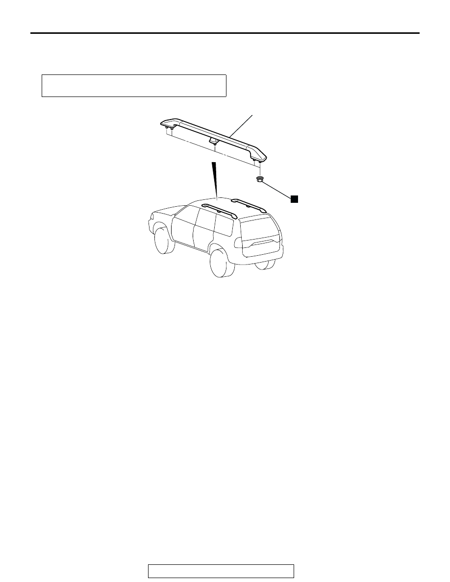
ROOF RAIL
REMOVAL AND INSTALLATION
M1511016600080
WINDSHIELD WIPER AND WASHER
GENERAL DESCRIPTION
M1511000100257
OPERATION
Low-speed (and high-speed) wiper operation
• When the wiper switch is placed in the "LOW"
position with the ignition switch in the "ACC" or
"ON" position, wipers operate continuously at low
speed.
• Placing the wiper switch in the "HIGH" position
causes the wipers to operate at high speed.
Auto wiper stop operation
• When the wiper switch is placed in the "OFF"
position, the cam contacts of wiper motor causes
current to flow through the auto wiper stop circuit,
allowing the wiper blades to cycle before they
reach to the stop positions.
Intermittent wiper operation
• When the wiper switch is placed in the "INTER-
MITTENT" position with the ignition switch in the
"ACC" or "ON" position, the intermittent wiper
relay is energized causing the intermittent wiper
relay contacts to close and open repeatedly.
• When the contacts are closed, the wiper motor is
energized.
• When the wiper motor is energized, the relay
contacts open; however, the cam contacts keep
the wiper motor energized until the wiper blades
return to their stop position.
Washer-wiper operation
• When the washer switch is turned "ON," the
intermittent wiper relay contacts close causing
wipers to cycle one to two times.
Pre-removal and Post-installation Operation
• Headlining Removal and Installation
AC200767
ROOF RAIL ASSEMBLY
AD
N