Mitsubishi Montero Sport (2004+). Manual - part 720


  Index      Mitsubishi     Mitsubishi Montero Sport - service repair manual 2004 year


Search            


Content   ..  718  719  720  721   ..


Mitsubishi Montero Sport (2004+). Manual - part 720


TRANSMISSION CONTROL

TSB Revision

AUTOMATIC TRANSMISSION

23A-445

TRANSMISSION CONTROL

REMOVAL AND INSTALLATION
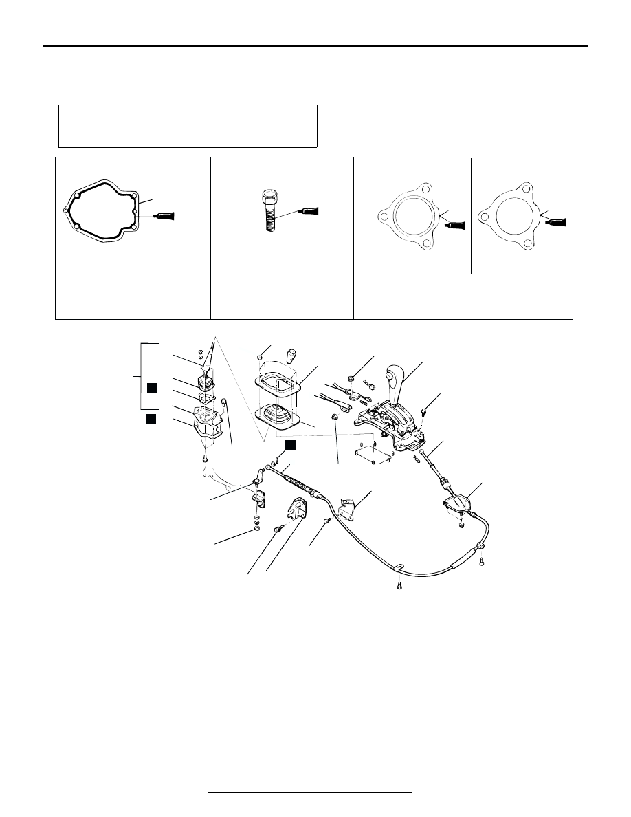
M1231117900123

Pre-removal and Post-installation Operation 
Floor Console Removal and Installation (Refer to GROUP 
52A, Floor Console 

P.52A-40

.)

AC004519

TRANSFER CONTROL LEVER
MOUNTING BOLT

APPLY SEALANT TO
CONTACT SURFACE
WITH TRANSFER
CONTROL LEVER

APPLY SEALANT
TO BOTH SIDES

SEALANT:
        3M™ AAD PART NO.8663 OR
        EQUIVALENT

SEALANT:
        3M™ AAD PART 
        NO.8730 OR EQUIVALENT

SEALANT:
        3M™ AAD PART 
        NO.8663 OR EQUIVALENT

5 N·m
44 in-lb

12 N·m
106 in-lb

12 N·m
106 in-lb

12 N·m
106 in-lb

24 N·m
18 ft-lb

24 N·m
18 ft-lb

12 N·m
106 in-lb

19 N·m
15 ft-lb

13

12

17

16
15
14
13

10

1

11

5

7

3

9

4

8

16

15

N

N

AC

2

N

6

SELECTOR LEVER ASSEMBLY 
REMOVAL STEPS

>>D<<

1.

KEY INTERLOCK CABLE 
CONNECTION

>>C<<

2.

SHIFT LOCK CABLE 
CONNECTION

3.

TRANSMISSION CONTROL 
CABLE ASSEMBLY 
CONNECTION (SELECTOR 
LEVER ASSEMBLY SIDE)

4.

SELECTOR LEVER

TRANSMISSION CONTROL 
CABLE ASSEMBLY REMOVAL 
STEPS

3.

TRANSMISSION CONTROL 
CABLE ASSEMBLY 
CONNECTION (SELECTOR 
LEVER ASSEMBLY SIDE)

5.

TRANSMISSION CONTROL 
UPPER LEVER

6.

TRANSMISSION CONTROL 
CABLE ASSEMBLY 
CONNECTION (TRANSMISSION 
SIDE)

TRANSMISSION CONTROL

TSB Revision

AUTOMATIC TRANSMISSION

23A-446

INSTALLATION SERVICE POINTS

.

>>A<< DUST COVER INSTALLATION
Install the dust cover so that it faces as shown in the illustration.

.

>>B<< TRANSMISSION CONTROL CABLE ASSEMBLY 
INSTALLATION
1. Shift the selector lever to the "N" position.
2. Place the transmission side lever in the "N" position.
3. Connect the transmission control cable to the selector lever.
4. Connect the upper lever to the transmission control cable.

7.

CABLE END BRACKET

8.

CABLE BRACKET <V4A51>

>>B<<

9.

TRANSMISSION CONTROL 
CABLE ASSEMBLY 

TRANSFER CONTROL LEVER 
ASSEMBLY REMOVAL STEPS

10.

RETAINER

>>A<<

11.

DUST COVER

12.

TRANSFER CONTROL LEVER 
ASSEMBLY

13.

GASKET

14.

STOPPER PLATE

15.

GASKET

16.

SPRING COVER SUPPORT

17.

TRANSFER CONTROL LEVER

TRANSMISSION CONTROL 
CABLE ASSEMBLY REMOVAL 
STEPS (Continued)

AC004520

FRONT

AB

AC004521AD

L

2

3

D

N

R

P

TRANSMISSION 
RANGE SWITCH

MANUAL
CONTROL
LEVER

TRANSMISSION CONTROL

TSB Revision

AUTOMATIC TRANSMISSION

23A-447

5. Temporarily tighten the nut while pressing the transmission 

control upper lever lightly in the direction of the arrow.

6. Tighten the nut with the specified torque.

Tightening torque: 24 N

m (18 ft-lb)

.

>>C<< SHIFT LOCK CABLE (SELECTOR LEVER SIDE) 
INSTALLATION
1. Shift the selector lever to the "P" position.
2. Fasten the shift lock cable at the position where the end of 

the shift lock cable is above the red line on the lock cam.

3. Tighten the nut with the specified torque.

Tightening torque: 12 N

m (106 in-lb)

4. Check that the shift lock mechanism operates normally. 

(Refer to 

P.23A-441

.)

.

>>D<< KEY INTERLOCK CABLE (SELECTOR LEVER SIDE) 
INSTALLATION
1. Shift the selector lever to the "P" position.
2. Turn the ignition switch to the "LOCK" (OFF) position.
3. Slide the washer and spring toward the lock cam, insert the 

cable into the stand off bracket and release the spring.

4. Lightly push the key interlock cable into the key interlock 

cable housing until the cable movement stops and the cable 
end eye is aligned with the shaft on the lock cam. Tighten 
the lock nut. Snap the cable end eye onto the shaft of the 
lock cam.

Tightening torque: 12 N

m (106 in-lb)

5. Check that the key interlock mechanism operates normally. 

(Refer to 

P.23A-440

.)

AC004522

TRANSMISSION
CONTROL 
UPPER LEVER

24 N·m
18 ft-lb

AB

AC004518

JAM NUT

LOCK CAM

SHIFT LOCK
CABLE

AC

MARKING (RED)

AC004517AC

JAM NUT

LOCK CAM

TRANSMISSION CONTROL

TSB Revision

AUTOMATIC TRANSMISSION

23A-448

INSPECTION

M1231118000123

Move the connector in the direction of the arrow and remove it 
from the bracket.
POSITION INDICATOR LIGHT CHECK

TESTER CONNECTION

SPECIFIED CONDITION

− 2

Less than 2 ohms

AC004523 AB

BRACKET

CONNECTOR


Content   ..  718  719  720  721   ..