Mitsubishi Montero Sport (2004+). Manual - part 719


  Index      Mitsubishi     Mitsubishi Montero Sport - service repair manual 2004 year


Search            


Content   ..  717  718  719  720   ..


Mitsubishi Montero Sport (2004+). Manual - part 719


ON-VEHICLE SERVICE

TSB Revision

AUTOMATIC TRANSMISSION

23A-441

SHIFT LOCK MECHANISM CHECK

M1232001000343

1. Perform the following inspections.

2. When any of the above shift lock inspection procedures fail, 

adjust the shift lock cable as follows:

(1) Remove the floor console. (Refer to GROUP 52A 

− Floor 

Console 

P.52A-40

.)

(2) Shift the selector lever to the "P" position.
(3) Loosen the lock nut on the shift lock cable.
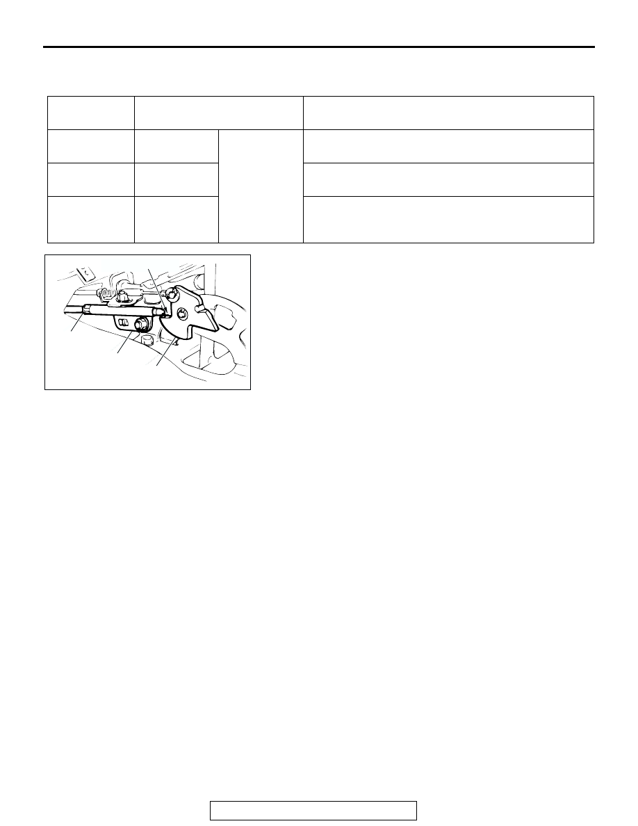
(4) Adjust the cable so that the end of the shift lock cable is 

above the red line on the lock cam and tighten the 
locknut.

Tightening torque: 12 N

m (106 in-lb)

(5) After adjusting, retest the shift lock cable operation. 

Replace the shift lock cable if it does not operate 
properly. (Refer to 

P.23A-451

.)

(6) Install the floor console.

AUTOMATIC TRANSMISSION CONTROL 
COMPONENT CHECK

CRANKSHAFT POSITION SENSOR CHECK

M1231102700145

Refer to GROUP 13A, Diagnosis 

− Check Procedure with 

Oscilloscope

P.13A-863

.

TP SENSOR CHECK

M1231102500152

Refer to GROUP 13A, On-vehicle Service 

− Throttle Position 

Sensor Check 

P.13A-890

.

INSPECTION 
PROCEDURE

CHECK CONTENTS

CHECK ITEM (NORMAL CONDITION)

1

Brake pedal: 
Not depressed

Ignition key 
position: "ACC"

When the selector lever push button is depressed, the 
selector lever can not be shifted out of the "P" position.

2

Brake pedal: 
Depressed

When the selector lever push button is depressed, the 
selector lever can be shifted smoothly to other positions.

3

Brake pedal: 
Not depressed

When the selector lever push button is depressed, the 
selector lever can be shifted smoothly from the "R" 
position to the "P position.

AC004518

JAM NUT

LOCK CAM

SHIFT LOCK
CABLE

AC

MARKING (RED)

ON-VEHICLE SERVICE

TSB Revision

AUTOMATIC TRANSMISSION

23A-442

TRANSMISSION FLUID TEMPERATURE SENSOR 
CHECK

M1231104200027

1. Remove the transmission fluid temperature sensor.
2. Measure the resistance between terminals No.1 and No.2 of 

the transmission fluid temperature sensor connector.

Standard value:

3. If the transmission fluid temperature sensor resistance is 

outside the specified range and the "A/T TEMP" indicator 
light is illuminating, replace the transmission fluid 
temperature sensor.
NOTE: The "A/T TEMP" indicator light on the combination 
meter illuminating when the temperature reaches approxi-
mately 125

°

C (257

°

F) or greater, and then stops illuminating 

when the temperature drops below approximately 115

°

(238

°

F).

TRANSMISSION RANGE SWITCH CHECK

M1231112600127

Refer to 

P.23A-435

.

STOPLIGHT SWITCH CHECK

M1231103000149

Refer to GROUP 35A, On-vehicle Service 

− Stoplight Switch 

Check 

P.35A-16

.

VEHICLE SPEED SENSOR CHECK

M1231109800132

Refer to GROUP 54, Combination Meters Assembly and Vehi-
cle Speed Sensor 

− Symptom Procedures − Speedometer 

does not work 

P.54-77

.

DUAL PRESSURE SWITCH CHECK

M1231109900139

Refer to GROUP 55A, On-vehicle Service 

− Dual Pressure 

Switch Check 

P.55-27

.

TRANSMISSION FLUID 
TEMPERATURE

RESISTANCE

0

°C (32°F)

16.7 

− 20.5 kΩ

20

°C (68°F)

7.3 

− 8.9 kΩ

40

°C (104°F)

3.4 

− 4.2 kΩ

60

°C (140°F)

1.9 

− 2.2 kΩ

80

°C (176°F)

1.0 

− 1.2 kΩ

100

°C (212°F)

0.57 

− 0.69 kΩ

AC100601AB

ATF

ON-VEHICLE SERVICE

TSB Revision

AUTOMATIC TRANSMISSION

23A-443

A/T CONTROL RELAY CHECK

M1231110300131

1. Remove the A/T control relay.

2. Use jumper wires to connect the A/T control relay terminal 2 

to the negative battery terminal and terminal 4 to the positive 
battery terminal.

3. Check for continuity between A/T control relay terminals 1 

and terminal 3 when the jumper wires are connected to and 
disconnected from the battery.

4. If there is any problem with the A/T control relay, replace it.

SOLENOID VALVE CHECK

M1231110400138

1. Use scan tool MB991502 to measure the transmission fluid 

temperature. The desired temperature setting for performing 
the solenoid valve check is 20

°C (68°F).

2. Remove the solenoid valve harness and transmission fluid 

temperature sensor connector.

3. Measure the resistance between the solenoid valve 

terminals.

4. The measured resistance of the solenoid valve when the 

transmission fluid temperature is 20

°C (68°F) should match 

the specified resistance on the chart below.

Standard value:

JUMPER WIRE

CONTINUITY BETWEEN 
TERMINALS NO.1 AND NO.3

Connected

Less than 2 ohms

Disconnected

Open circuit

AC002590AD

A/T CONTROL
RELAY

AC100555

1 2
3 4

AC

TERMINAL 
NO.

ITEM

RESISTANCE

7 - 10

Torque converter clutch 
solenoid valve

2.7 

− 3.4 Ω [at 

20

°C (68°F)]

6 - 10

Low-reverse solenoid valve 

4 - 9

Second solenoid valve

3 - 9

Underdrive solenoid valve

5 - 9

Overdrive solenoid valve

AC103397

7

10

5

3

1 2

4

6

9

8

SOLENOID VALVE
HARNESS AND 
TRANSMISSION FLUID
TEMPERATURE SENSOR
CONNECTOR

AC

ON-VEHICLE SERVICE

TSB Revision

AUTOMATIC TRANSMISSION

23A-444

5. If the solenoid valve resistance is within the specified range, 

check the power supply and the ground circuits.

6. If the solenoid valve resistance is not within the specified 

range, drain the transmission fluid and remove the valve 
body cover.

7. Disconnect the connector of any solenoid valves that are not 

within the specified range. 

8. Measure the resistance between terminals 1 and 2 of any 

solenoid valve that was not within the specified range.

Specified resistance:

2.7 

 3.4  [at 20°C (68°F)]

9. If the resistance is not within the specified range, replace the 

solenoid valve.

10.If the resistance is within the specified range, check the 

wiring harness between the affected A/T control solenoid 
valve assembly and the solenoid valve. If a problem is not 
found in the above steps, check the solenoid valve O-rings 
and replace them if necessary.

AC100378

1
2

AB

ACX01206AC

TORQUE CONVERTER 
CLUTCH SOLENOID 
VALVE

UNDERDRIVE 
SOLENOID VALVE

LOW-REVERSE 
SOLENOID VALVE

OVERDRIVE 
SOLENOID 
VALVE

SECOND 
SOLENOID VALVE


Content   ..  717  718  719  720   ..