Mitsubishi Montero Sport (2004+). Manual - part 669


  Index      Mitsubishi     Mitsubishi Montero Sport - service repair manual 2004 year


Search            


Content   ..  667  668  669  670   ..


Mitsubishi Montero Sport (2004+). Manual - part 669


AUTOMATIC TRANSMISSION DIAGNOSIS

TSB Revision

AUTOMATIC TRANSMISSION

23A-241

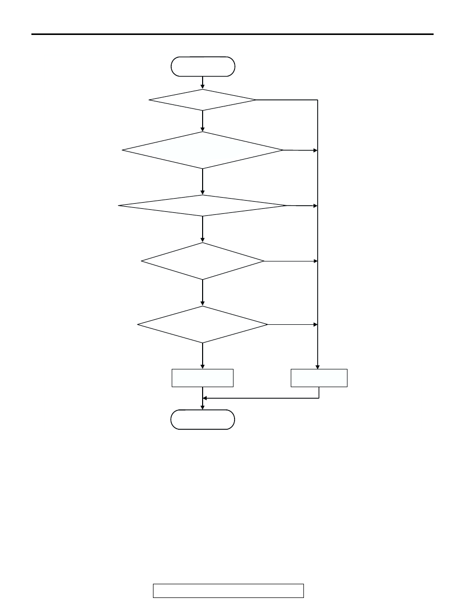
LOGIC FLOW CHARTS (Monitor Sequence)

.

DTC SET CONDITIONS

Check Conditions

• Solenoid status: either solid ON or OFF.

• Shift status: in-gear.

• Voltage of battery: 10 volts or more.

Judgement Criteria

• Solenoid voltage: 3 volts or less. (0.3 second)

• If DTC 32 (P0758) is set consecutively four times, 

the transmission is locked into 3rd gear as a 
fail-safe measure, and the "N" range light flashes 
once per second.

.

OBD-II DRIVE CYCLE PATTERN
Start the engine, and keep the vehicle stopped in P 
range for 5 seconds.

.

TROUBLESHOOTING HINTS (The most likely 
causes for this code to be set are:)

• Malfunction of underdrive solenoid valve

• Damaged harness, connector

• Malfunction of the PCM

AC205282

Good

Malfunction

END

START

In-gear?

Shift solenoid-B is in ON 
or OFF steady state

Voltage of battery > 10 V

Solenoid circuit 
voltage < 3 V

Continuous failure 
for 0.3 sec.

Yes

No

Yes

No

Yes

No

Yes

No

Yes

No

  Underdrive solenoid valve
is in ON or OFF steady state

AB

AUTOMATIC TRANSMISSION DIAGNOSIS

TSB Revision

AUTOMATIC TRANSMISSION

23A-242

DIAGNOSIS

Required Special Tool:

• MB991958: Scan Tool (MUT-III Sub Assembly)

• MB991824: V.C.I.

• MB991827: MUT-III USB Cable

• MB991911: MUT-III Main Harness B

STEP 1. Using scan tool MB991958, check actuator test 
item 02: Underdrive Solenoid Valve.

CAUTION

To prevent damage to scan tool MB991958, always turn the 
ignition switch to the "LOCK" (OFF) position before con-
necting or disconnecting scan tool MB991958.
(1) Connect scan tool MB991958 to the data link connector.
(2) Turn the ignition switch to the "ON" position.
(3) Set scan tool MB991958 to actuator test mode.

• Item 02: Underdrive Solenoid Valve.

• An audible clicking or buzzing should be heard when 

the underdrive solenoid valve is energized.

(4) Turn the ignition switch to the "LOCK" (OFF) position.
Q: Is the solenoid valve operating properly?

YES : It can be assumed that this malfunction is intermittent. 

Refer to GROUP 00, How to Use 
Troubleshooting/Inspection Service Points 

− How to 

Cope with Intermittent Malfunctions 

P.00-7

.

NO :  Go to Step 2.

AK303629AB

MB991911

MB991827

MB991824 

16-PIN

AUTOMATIC TRANSMISSION DIAGNOSIS

TSB Revision

AUTOMATIC TRANSMISSION

23A-243

STEP 2. Using scan tool MB991958, read the A/T 
diagnostic trouble code.

(1) Connect scan tool MB991958 to the data link connector.
(2) Turn the ignition switch to the "ON" position.
(3) Check for A/T diagnostic trouble code.
(4) Turn the ignition switch to the "LOCK" (OFF) position.
Q: Is DTC 54 set? (DTC 54 may be set along with multiple 

DTCs).
YES : 
Refer to 

P.23A-319

 DTC 54: A/T Control Relay 

System.

NO :  Go to Step 3.

STEP 3. Using scan tool MB991958, read the A/T 
diagnostic trouble code.

(1) Connect scan tool MB991958 to the data link connector.
(2) Turn the ignition switch to the "ON" position.

(3) Check for A/T diagnostic trouble code.
(4) Turn the ignition switch to the "LOCK" (OFF) position.
Q: Are DTC 33 and DTC 34 set? (Multiple DTCs may be set).

YES : Go to Step 8.
NO :  Go to Step 4.

AK303629AB

MB991911

MB991827

MB991824 

16-PIN

AK303629AB

MB991911

MB991827

MB991824 

16-PIN

AUTOMATIC TRANSMISSION DIAGNOSIS

TSB Revision

AUTOMATIC TRANSMISSION

23A-244

STEP 4. Measure the underdrive solenoid valve resistance 
at A/T control solenoid valve assembly connector B-02.

(1) Disconnect connector B-02 and measure at the solenoid 

valve side.

(2) Measure the resistance between solenoid valve assembly 

connector B-02 terminals 3 and 9.

Resistance value: 2.7 

 3.4  [at 20°C (68°F)]

Q: Is the measured resistance 2.7 

 3.4  [at 20°C (68°F)]?

YES : Go to Step 6.
NO :  Go to Step 5.

STEP 5. Measure the solenoid valve resistance at the 
underdrive solenoid valve connector B-02-1 inside the 
transmission.

(1) Disconnect solenoid valve connector B-02-1 and measure 

at the solenoid valve side.

(2) Measure the resistance between underdrive solenoid valve 

terminals 1 and 2.

Resistance value: 2.7 

 3.4  [at 20°C (68°F)]

Q: Is the measured resistance 2.7 

 3.4  [at 20°C (68°F)?

YES : Replace the harness wire between A/T control 

solenoid valve assembly connector B-02 and the 
solenoid valves.

NO :  Replace the underdrive solenoid valve. Refer to 

GROUP 23B, Valve Body 

P.23B-67

.

AC202437

6

10

4

9

5

3

8

2

7

1

CONNECTOR:B-02

AB

B-02 (B)

TRANSMISSION
CONTROL CABLE

AC001962

AJ

B-02 HARNESS CONNECTOR:
A/T CONTROL SOLENOID SIDE 

AC004272AP

2

1

CONNECTOR : B-02-1

2

1

AC201141BK

B-02-1 HARNESS CONNECTOR : 
UNDERDRIVE SOLENOID 
VALVE SIDE


Content   ..  667  668  669  670   ..