Mitsubishi Montero Sport (2004+). Manual - part 640


  Index      Mitsubishi     Mitsubishi Montero Sport - service repair manual 2004 year


Search            


Content   ..  638  639  640  641   ..


Mitsubishi Montero Sport (2004+). Manual - part 640


AUTOMATIC TRANSMISSION DIAGNOSIS

TSB Revision

AUTOMATIC TRANSMISSION

23A-125

DESCRIPTIONS OF MONITOR METHODS
If no signal is input from transmission range switch 
for more than 30 seconds, PCM judges that trans-
mission range switch has a failure.

.

MONITOR EXECUTION
Continuous

.

MONITOR EXECUTION CONDITIONS (Other 
monitor and Sensor)

Other Monitor (There is no temporary DTC stored 

in memory for the item monitored below)

• Not applicable

Sensor (The sensor below is determined to be 

normal)

• Not applicable

.

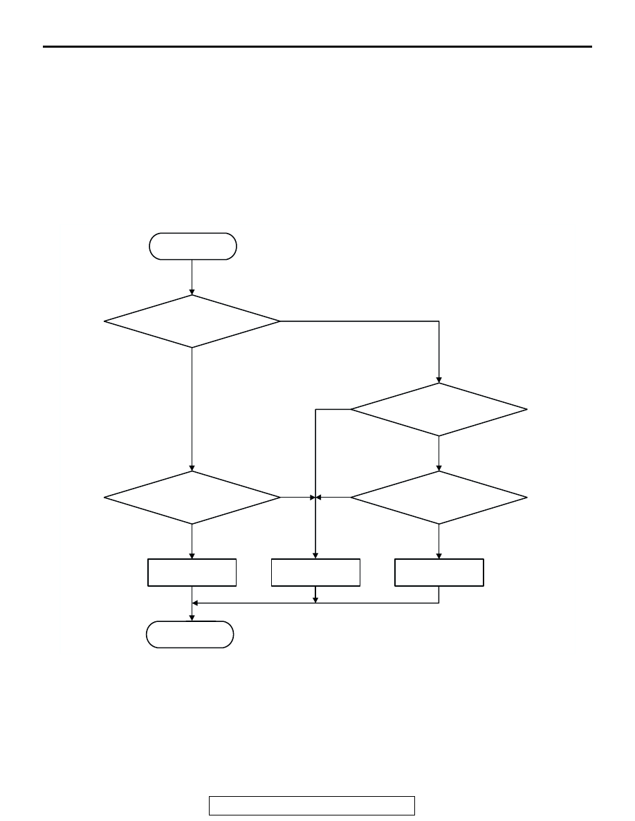
LOGIC FLOW CHARTS (Monitor Sequence)

.

DTC SET CONDITIONS

Check Conditions, Judgement Criteria

• Transmission range switch: no signal detected. 

(30 seconds)

.

OBD-II DRIVE CYCLE PATTERN
Start the engine, keep the vehicle stopped in P, R, N, 
D, 3, 2 and L ranges respectively for more than one 
minute, and turn "LOCK" (OFF) the ignition switch. 
Then restart the engine, and stop the vehicle in P, R, 
N, D, 3, 2 and L ranges respectively for more than 
one minute.

.

AC205064

START

Is there no
input signal?

Yes

No

Continuous failure
for 30 secs.

Yes

Yes

Yes

No

No

No

Continuous failure
for 30 secs.

Is there more than
one input signal?

Malfunction

Good

Malfunction

END

AUTOMATIC TRANSMISSION DIAGNOSIS

TSB Revision

AUTOMATIC TRANSMISSION

23A-126

TROUBLESHOOTING HINTS (The most likely 
causes for this code to be set are:)

• Malfunction of the transmission range switch

• Malfunction of the ignition switch

• Damaged harness, connector

• Malfunction of the PCM

DIAGNOSIS

Required Special Tool:

• MB991958: Scan Tool (MUT-III Sub Assembly)

• MB991824: V.C.I.

• MB991827: MUT-III USB Cable

• MB991911: MUT-III Main Harness B

STEP 1. Using scan tool MB991958, check data list item 61: 
Transmission Range Switch.

CAUTION

To prevent damage to scan tool MB991958, always turn the 
ignition switch to the "LOCK" (OFF) position before con-
necting or disconnecting scan tool MB991958.
(1) Connect scan tool MB991958 to the data link connector.
(2) Turn the ignition switch to the "ON" position.
(3) Set scan tool MB991958 to data reading mode.

• Item 61: Transmission Range Switch.

• Move the selector lever to the "P," "R," "N," "D," "3," 

"2," "L" positions and confirm that the selected trans-
mission ranges match the positions shown on scan 
tool MB991958.

(4) Turn the ignition switch to the "LOCK" (OFF) position.
Q: Is the switch operating properly?

YES : It can be assumed that this malfunction is intermittent. 

Refer to GROUP 00, How to Use 
Troubleshooting/Inspection Service Points 

− How to 

Cope with Intermittent Malfunction 

P.00-7

.

NO (no correct transmission range is displayed) : Go to 

Step 2.

NO (Only "P" position is not displayed correctly) : Go to 

Step 6.

NO (Only "R" position is not displayed correctly) : Go to 

Step 14.

NO (Only "N" position is not displayed correctly) : Go to 

Step 21.

NO (Only "D" position is not displayed correctly) : Go to 

Step 28.

NO (Only "3" position is not displayed correctly) : Go to 

Step 35.

NO (Only "2" position is not displayed correctly) : Go to 

Step 42.

NO (Only "L" position is not displayed correctly) : Go to 

Step 49.

AK303629AB

MB991911

MB991827

MB991824 

16-PIN

AUTOMATIC TRANSMISSION DIAGNOSIS

TSB Revision

AUTOMATIC TRANSMISSION

23A-127

STEP 2. Check the transmission range switch.

Measure the resistance between the terminals for each trans-
mission range as indicated in the table below.

Q: Is the measured resistance less than 2 ohms for each 

selector position?
YES : 
Go to Step 3.
NO :  Replace the transmission range switch. Refer to 

GROUP 23B, Transmission 

P.23B-19

.

TRANSMISSION 
RANGE

TERMINAL 
CONNECTION OF 
TESTER

SPECIFIED 
CONDITION

P

− 7

Less than 2 ohms.

R

− 8

N

− 7

D

− 7

3

− 7

2

− 7

L

− 7

AC202393

4
9

5

10

3
8

2
7

6

1

CONNECTOR: B-01
<RWD>

<4WD>

B-01 (B)

B-01 (B)

AB

AC004076

P

R

N

D

3
2

L

AB

AUTOMATIC TRANSMISSION DIAGNOSIS

TSB Revision

AUTOMATIC TRANSMISSION

23A-128

STEP 3. Check transmission range switch connector B-01, 
intermediate connector C-30 and junction block connector 
D-13 for loose, corroded or damaged terminals, or 
terminals pushed back in the connector.

Q: Are the connectors and terminals in good condition?

YES : Go to Step 4.
NO :  Repair or replace the damaged components. Refer to 

GROUP 00E, Harness Connector Inspection 

P.00E-2

.

AC202393

4
9

5

10

3
8

2
7

6

1

CONNECTOR: B-01
<RWD>

<4WD>

B-01 (B)

B-01 (B)

AB

AC202367

JUNCTION BLOCK (REAR)

4

3

10 11

9

8

5

12

1
6

2
7

19 20

6

17

7

5

15

14

16

8

18

3

11 12

4

2

10

1

9

13

CONNECTORS: C-30, D-13

D-13

D-13

C-30

C-30

AB


Content   ..  638  639  640  641   ..