Mitsubishi Montero Sport (2004+). Manual - part 638


  Index      Mitsubishi     Mitsubishi Montero Sport - service repair manual 2004 year


Search            


Content   ..  636  637  638  639   ..


Mitsubishi Montero Sport (2004+). Manual - part 638


AUTOMATIC TRANSMISSION DIAGNOSIS

TSB Revision

AUTOMATIC TRANSMISSION

23A-117

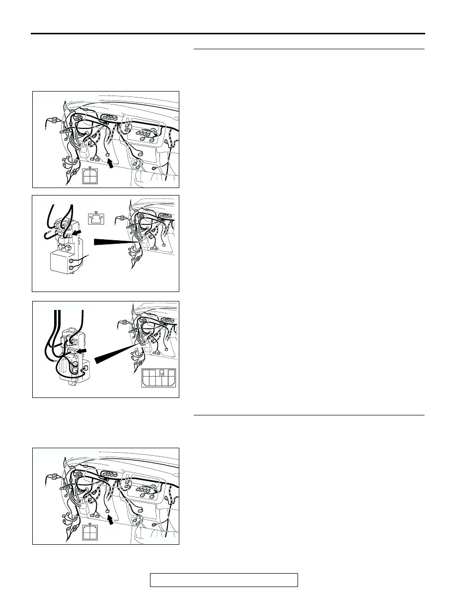
STEP 5. Check stoplight switch connector C-66, junction 
block connector D-02 and D-09 for loose, corroded or 
damaged terminals, or terminals pushed back in the 
connector.

Q: Are the connectors and terminals in good condition?

YES : Go to Step 6.
NO :  Repair or replace the damaged components. Refer to 

GROUP 00E, Harness Connector Inspection 

P.00E-2

.

STEP 6. Check the harness for damage between stoplight 
switch connector C-66 terminal 2 and the power supply 
fuse.

Q: Is the harness wire in good condition?

YES : Go to Step 7.
NO :  Repair or replace the harness wire.

AC309389

CONNECTOR: C-66

C-66 (B)

AB

1
3 4

2

AC202390

JUNCTION BLOCK (FRONT)

1

D-02 (GR)

AB

CONNECTOR: D-02

AC202391

JUNCTION BLOCK (REAR)

7 8

2

3

6

5

1

4

CONNECTOR: D-09

D-09

AB

AC309389

CONNECTOR: C-66

C-66 (B)

AB

1
3 4

2

AUTOMATIC TRANSMISSION DIAGNOSIS

TSB Revision

AUTOMATIC TRANSMISSION

23A-118

STEP 7. Measure the stoplight switch output voltage to the 
PCM at connector C-66 by backprobing.

(1) Remove the stoplight switch from the mounting bracket.
(2) Do not disconnect connector C-66.

(3) Measure the voltage between stoplight switch connector 

C-66 terminal 3 and ground by backprobing.

• When the switch button is out (closed circuit), voltage 

should equal battery positive voltage.

• When the switch button is depressed (open circuit), volt-

age should measure less than 1.0 volt.

Q: Is the measured voltage battery positive voltage with 

the switch button released (closed circuit), and less 
than 1.0 volt with the switch button depressed (open 
circuit)?
YES : 
Go to Step 9.
NO :  Go to Step 8.

STEP 8. Check the stoplight switch.

Refer to GROUP 35A, On-vehicle Service 

− Stoplight Switch 

Check 

P.35A-16

.

Q: Does the stoplight switch pass the checks?

YES : Go to Step 9.
NO :  Replace the stoplight switch. Refer to GROUP 35A, 

Brake Pedal 

P.35A-27

.

AC309389

CONNECTOR: C-66

C-66 (B)

AB

1
3 4

2

AC203805

1
2

2
4

1

3

AC

C-66 HARNESS CONNECTOR:
HARNESS SIDE

ACX02208

BRAKE PEDAL

STOPLIGHT
SWITCH

AD

AUTOMATIC TRANSMISSION DIAGNOSIS

TSB Revision

AUTOMATIC TRANSMISSION

23A-119

STEP 9. Measure the stoplight switch output voltage at 
PCM connector C-92 by backprobing.

(1) Install the stoplight switch into the mounting bracket if it was 

removed.

(2) Do not disconnect connector C-92.

(3) Measure the voltage between terminal 123 and ground by 

backprobing.

• When the brake pedal is depressed, voltage should 

measure battery positive voltage.

• When the brake pedal is not depressed, voltage should 

measure less than 1.0 volt.

Q: Is the measured voltage battery positive voltage with 

the brake pedal depressed (closed circuit), and less 
than 1.0 volt with the brake pedal released (open 
circuit)?
YES : 
Go to Step 12.
NO :  Go to Step 10.

AC202317

PCM

120

107

119

106

129 130

118

105

117

114115116

126127128

104

111

103

112

108

101102

109110

121122123

124

113

125

CONNECTOR: C-92

C-92 (GR)

AB

AC001812

C-92 HARNESS CONNECTOR:
HARNESS SIDE

AJ

AUTOMATIC TRANSMISSION DIAGNOSIS

TSB Revision

AUTOMATIC TRANSMISSION

23A-120

STEP 10. Check intermediate connector C-85 and PCM 
connector C-92 for loose, corroded or damaged terminals, 
or terminals pushed back in the connector.

Q: Are the connectors and terminals in good condition?

YES : Go to Step 11.
NO :  Repair or replace the damaged components. Refer to 

GROUP 00E, Harness Connector Inspection 

P.00E-2

.

AC202389

11

4

3

9

8

10

5 6

2

1

7

CONNECTOR: C-85

C-85

AB

AC202317

PCM

120

107

119

106

129 130

118

105

117

114115116

126127128

104

111

103

112

108

101102

109110

121122123

124

113

125

CONNECTOR: C-92

C-92 (GR)

AB


Content   ..  636  637  638  639   ..