Mitsubishi Montero Sport (2004+). Manual - part 600


  Index      Mitsubishi     Mitsubishi Montero Sport - service repair manual 2004 year


Search            


Content   ..  598  599  600  601   ..


Mitsubishi Montero Sport (2004+). Manual - part 600


ON-VEHICLE SERVICE

TSB Revision

HEATER, AIR CONDITIONING AND VENTILATION

55-27

ON-VEHICLE SERVICE

REFRIGERANT LEVEL TEST

M1552008400271

Use the refrigerant recovery station to remove all of the refrig-
erant, and then calculate the amount of the refrigerant and 
charge it.

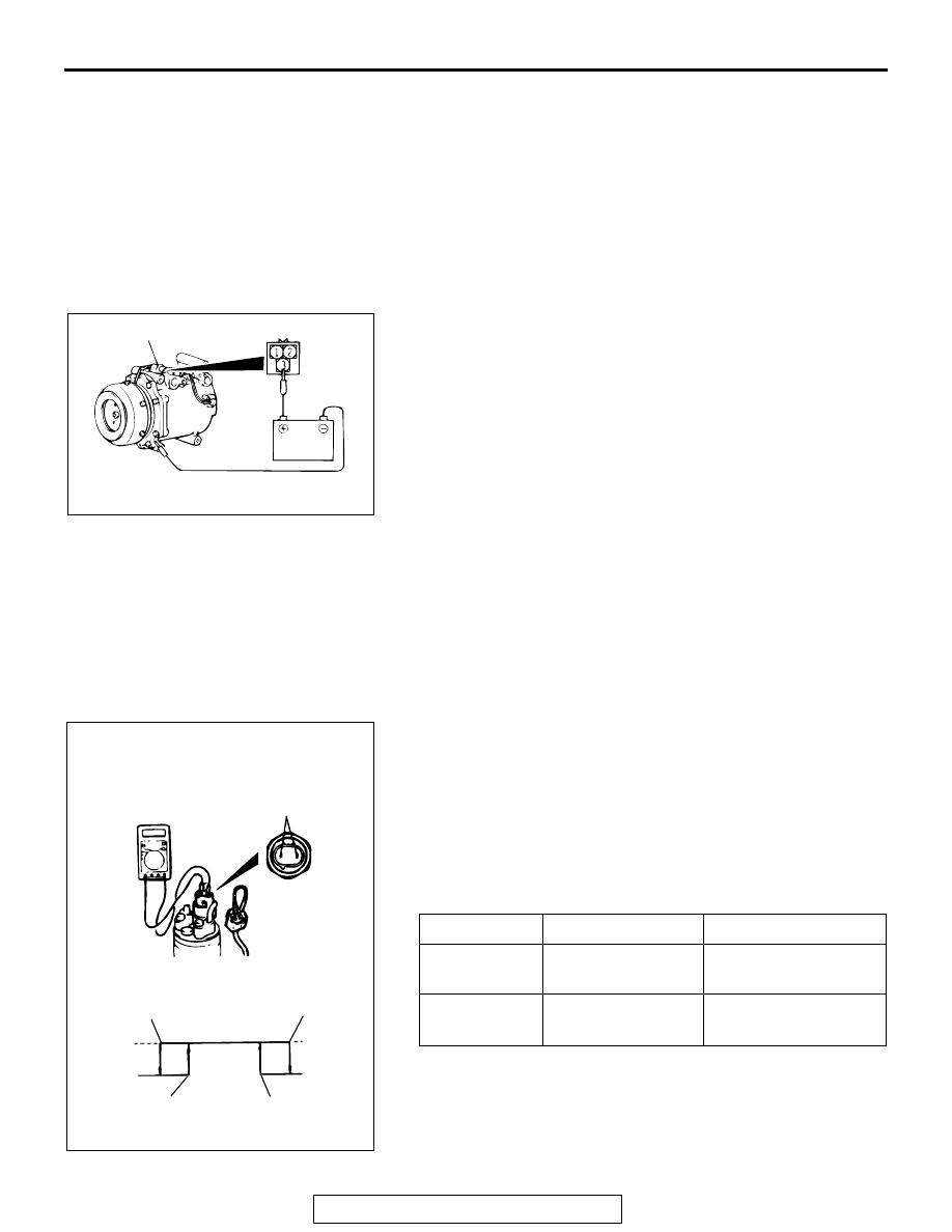
A/C COMPRESSOR CLUTCH TEST

M1552019900076

1. Disconnect the A/C compressor clutch connector to the A/C 

compressor clutch.

2. Connect positive battery voltage directly to the connector for 

the A/C compressor clutch.

3. If the A/C compressor clutch is normal, there will be a "click." 

If the pulley and armature do not make contact ("click"), 
there is a malfunction.

RECEIVER DRIER TEST

M1552008600220

Turn the A/C on. Check the temperature by touching the 
receiver drier outlet and inlet pipes. If there is a difference in the 
temperatures of the two pipes, the receiver assembly is 
restricted. Replace the receiver assembly.

DUAL PRESSURE SWITCH CHECK

M1552010400364

1. Remove the dual pressure switch connector and connect 

the high/low pressure side terminals located on the harness 
side as shown in the illustration.

2. Install a gauge manifold to the high-pressure side service 

valve of the refrigerant line. (Refer to 

P.55-29

.)

3. When the high/low pressure sides of the dual pressure 

switch are at operation pressure (ON) and there is continuity 
between the respective terminals, then the condition is 
normal. If there is no continuity, replace the switch.

AC002842

A/C COMPRESSOR CLUTCH

CONNECTOR

AC

ITEM

FROM OFF TO ON FROM ON TO OFF

Low-pressure 
side kPa (psi)

221 

± 27 (32.1 ± 

3.9)

196 

± 20 (28.4 ± 2.9)

High-pressure 
side kPa (psi)

2,354 

± 200 (341.4 

± 29)

2,942 

± 200 (426.7 ± 

29)

A003021

HIGH/LOW
PRESSURE SIDE

LOW-PRESSURE
SIDE

HIGH-PRESSURE
SIDE

ON

OFF

ON

OFF

AC

196 ± 20
(28.4 ± 2.9)

221 ± 27
(32.1 ± 3.9)

kPa (psi)

2942 ± 200
(426.7 ± 29)

2354 ± 200
(341.4 ± 29)

ON-VEHICLE SERVICE

TSB Revision

HEATER, AIR CONDITIONING AND VENTILATION

55-28

COMPRESSOR DRIVE BELT ADJUSTMENT

M1552001000249

Refer to GROUP 00, Maintenance Service 

− Drive Belts 

P.00-46

.

CHARGING 

M1552001200254

Use the refrigerant recovery station to charge the refrigerant.

METHOD BY USING REFRIGERANT RECOVERY 
AND RECYCLING UNIT

Using the refrigerant recovery and recycling unit, refill the 
refrigerant.
NOTE: Refer to the Refrigerant Recovery and Recycling Unit 
Instruction Manual for operation of the unit.

DISCHARGING SYSTEM

Use the refrigerant recovery unit to discharge refrigerant gas 
from the system.
NOTE: Refer to the Refrigerant Recovery and Recycling Unit 
Instruction Manual for operation of the unit.

REFILLING OF OIL IN THE A/C SYSTEM

Too little oil will provide inadequate compressor lubrication and 
cause a compressor failure. Too much oil will increase dis-
charge air temperature.
When a compressor is installed at the factory, it contains 170 
cm

3

 (5.7 floz) of refrigerant oil. While the A/C system is in oper-

ation, the oil is carried through the entire system by the refriger-
ant. Some of this oil will be trapped and retained in various 
parts of the system.
When the following system components are replaced, it is nec-
essary to add oil to the system to replace the oil being removed 
with the component.

Compressor oil: SUN PAG 56
Quantity:

• Evaporator: 20 cm

3

 (0.7 floz)

• Condenser: 70 cm

3

 (2.4 floz)

• Suction hose: 10 cm

3

 (0.3 floz)

• Receiver: 10 cm

3

 (0.3 floz)

ON-VEHICLE SERVICE

TSB Revision

HEATER, AIR CONDITIONING AND VENTILATION

55-29

PERFORMANCE TEST 

M1552001400418

1. The vehicle to be tested should be in a place that is not in 

direct sunlight.

2. Close the high and low-pressure valve of the gauge 

manifold.

3. Connect the charging hose (blue) to the low-pressure valve 

and connect the charging hose (red) to the high-pressure 
valve of the gauge manifold.

4. Install the quick joint (for low-pressure) to the charging hose 

(blue), and connect the quick joint (for high-pressure) to the 
charging hose (red).

CAUTION

• To connect the quick joint, press section A firmly 

against the service valve until a click is heard.

• When connecting, run your hand along the hose while 

pressing to ensure that there are no bends in the hose.

5. Connect the quick joint (for low-pressure) to the 

low-pressure service valve and connect the quick joint (for 
high-pressure) to the high-pressure service valve.
NOTE: The high-pressure service valve is on A/C pipe and 
the low-pressure service valve is on the suction hose.

6. Start the engine.
7. Set the A/C controls as follows:

• A/C switch: A/C − ON position

• Mode selection: FACE position

• Temperature control: MAXIMUM COOLING position

• Air selection: RECIRCULATION position

• Blower switch: HI position 

8. Adjust engine speed to 1,000 r/min with A/C compressor 

clutch engaged.

9. Engine should be warmed up with doors and windows 

closed.

10.Insert the thermistor-type thermometer into the discharge 

port shown left and measure the discharge air temperature.

11.Note the discharge air temperature.

NOTE: If the clutch cycles, take the reading before the 
clutch disengages.

AC001388

LOW-PRESSURE
VALVE

HIGH-PRESSURE
VALVE

GAUGE MANIFOLD

CHARGING
HOSE (RED)

A

SLEEVE

CHARGING
HOSE (BLUE)

ADAPTOR
VALVE
(FOR
LOW-PRES-
SURE)

ADAPTOR
VALVE
(FOR HIGH-
PRESSURE)

LOW-
PRESSURE
SERVICE
VALVE

HIGH-
PRESSURE
SERVICE
VALVE

AB

AC003023AB

THERMOMETER

ON-VEHICLE SERVICE

TSB Revision

HEATER, AIR CONDITIONING AND VENTILATION

55-30

Performance Temperature Chart

REFRIGERANT LEAK REPAIR

M1552001500329

LOST CHARGE

If the system has lost all charge due to a leak:
1. Evacuate the system. (See procedure.)
2. Charge the system with  0.453 kg (1 pound) of 

refrigerant.

3. Check for leaks.
4. Discharge the system.
5. Repair leaks.

CAUTION

Replacement filter-drier units must be sealed 
while in storage. The drier used in these units will 
saturate water quickly upon exposure to the 
atmosphere. When installing a drier, have all 
tools and supplies ready for quick assembly to 
avoid keeping the system open any longer than 
necessary.
6. Replace receiver drier.
7. Evacuate and charge system.

LOW CHARGE

If the system has not lost all of its refrigerant charge, 
locate and repair all leaks. If it is necessary to 
increase the system pressure to find the leak 
(because of an especially low charge) add refriger-
ant. If it is possible to repair the leak without dis-
charging the refrigerant system, use the procedure 
for correcting low refrigerant level.

HANDLING TUBING AND FITTINGS

Kinks in the refrigerant tubing or sharp bends in the 
refrigerant hose lines will greatly reduce the capacity 
of the entire system. High pressures are produced in 
the system when it is operating. Extreme care must 
be exercised to make sure that all connections are 
pressure tight. Dirt and moisture can enter the sys-
tem when it is opened for repair or replacement of 
lines or components. The following precautions must 
be observed. The system must be completely dis-
charged before opening any fitting of connection in 
the refrigeration system. Open fittings with caution 
even after the system has been discharged. If any 
pressure is noticed as a fitting is loosened, allow 
trapped pressure to bleed off very slowly.
Never attempt to rebend formed lines to fit. Use the 
correct line for the installation you are servicing. A 
good rule for the flexible hose lines is keep the radius 
of all bends at least 10 times the diameter of the 
hose.
Sharper bends will reduce the flow of refrigerant. The 
flexible hose lines should be routed so that they are 
at least 80 mm (3.1 inches) from the exhaust mani-
fold. It is good practice to inspect all flexible hose 
lines at least once a year to make sure they are in 
good condition and properly routed.
On standard plumbing fittings with O-rings, these 
O-rings are not reusable.

GARAGE AMBIENT 
TEMPERATURE 

°C (°F)

20 (68)

25 (77)

35 (95)

40 (104)

Discharge air 
temperature 

°C (°F)

4.9 

− 6.5

(40.1 

− 43.7)

5.0 

− 7. 0

(41.0 

− 44.6)

7.2 

− 9.2 (45.0 − 

48.6)

8.5 

− 10.5 (47.3 − 

50.9)

Compressor high 
pressure kPa (psi)

830 

− 1,130 (120 − 

164)

1,000 

− 1,300 (145 

−189)

1,200 

− 1,500 (174 

− 218)

1,550 

− 1850 (225 

− 268)

Compressor low 
pressure kPa (psi)

95 

− 195 (14 − 28) 105 − 209 (15 − 

30)

125 

− 229 (18 − 

33)

145 

− 245 (21 − 

36)


Content   ..  598  599  600  601   ..