Mitsubishi Montero Sport (2004+). Manual - part 598


  Index      Mitsubishi     Mitsubishi Montero Sport - service repair manual 2004 year


Search            


Content   ..  596  597  598  599   ..


Mitsubishi Montero Sport (2004+). Manual - part 598


MANUAL A/C DIAGNOSIS

TSB Revision

HEATER, AIR CONDITIONING AND VENTILATION

55-19

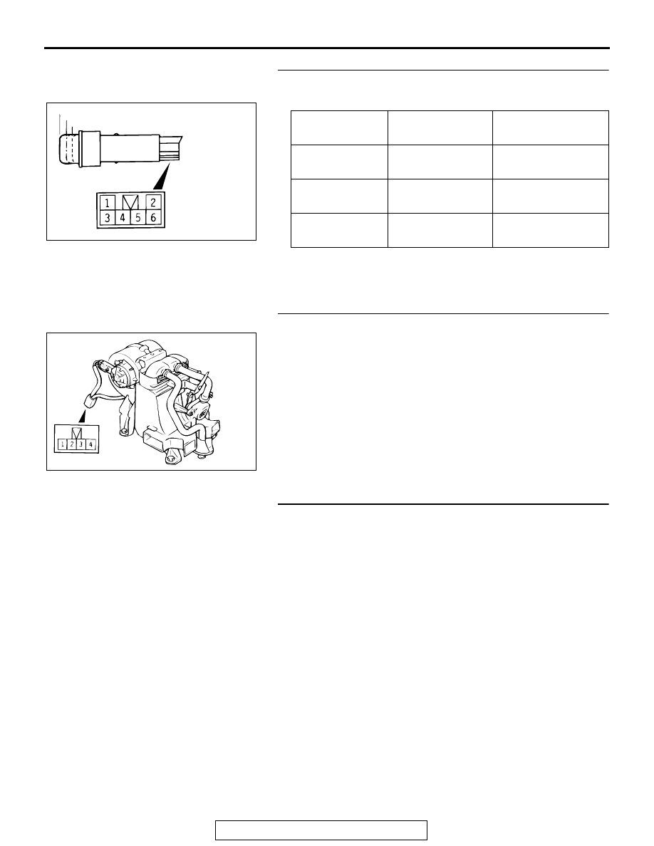
STEP 3. Check the rear heater switch continuity.

Remove the rear heater switch and check continuity.

Q: Is the rear heater switch normal?

YES : Go to Step 4. 
NO :  Replace. Then go to Step 5.

STEP 4. Check the resister resistance value.

Use an ohmmeter to check the resistance between terminals 
number 3 and 4. Check that the measured value is at the stan-
dard value.

Standard value: 3.9

Q: Is the resistance value correct? 

YES : The procedure is complete. (If no malfunctions are 

found in all steps, an intermittent malfunction is 
suspected. Refer to GROUP 00, How to Use 
Troubleshooting/Inspection Service Points 

− How to 

Cope with Intermittent Malfunction 

P.00-7

.)

NO :  Replace. Then go to Step 5. 

STEP 5. Retest the system.
NOTE: The condenser fan might not operate when there is an 
air conditioning low load from the air conditioning condenser 
control, so remove the negative battery terminal and then 
check the symptoms after 5 minutes since initial start control 
after reconnection.
Q: Is the condenser fan operating correctly?

YES : The procedure is complete.
NO :  Go to Step 1.

SWITCH 
POSITION

TESTER 
CONNECTION

SPECIFIED 
CONDITION

At the "OFF" 
position

− 4

− 4

Open circuit

At the "LO" 
position

− 4

Less than 2 ohms

At the "HI" 
position

− 4

Less than 2 ohms

AC002861

LO

OFF

HI

AC

AC002863AB

MANUAL A/C DIAGNOSIS

TSB Revision

HEATER, AIR CONDITIONING AND VENTILATION

55-20

INSPECTION PROCEDURE 8: The Rear Heater Air Volume cannot be Controlled in Two Steps.

DIAGNOSIS

STEP 1. Check the rear heater switch continuity.

Remove the rear heater switch and check continuity.

Q: Is the rear heater switch normal?

YES : Go to Step 2. 
NO :  Replace. Then go to Step 3. 

STEP 2. Check the resister resistance value.

Use an ohmmeter to check the resistance between terminals 
number 3 and 4. Check that the measured value is at the stan-
dard value.

Standard value: 3.9 

Q: Is the resistance value correct? 

YES : The procedure is complete. (If no malfunctions are 

found in all steps, an intermittent malfunction is 
suspected. Refer to GROUP 00, How to Use 
Troubleshooting/Inspection Service Points 

− How to 

Cope with Intermittent Malfunction 

P.00-7

.)

NO :  Replace. Then go to Step 3. 

STEP 3. Retest the system.
NOTE: The condenser fan might not operate when there is an 
air conditioning low load from the air conditioning condenser 
control, so remove the negative battery terminal and then 
check the symptoms after 5 minutes since initial start control 
after reconnection.
Q: Is the condenser fan operating correctly?

YES : The procedure is complete.
NO :  Go to Step 1.  

SWITCH 
POSITION

TESTER 
CONNECTION

SPECIFIED 
CONDITION

At the "OFF" 
position

− 4

− 4

Open circuit

At the "LO" 
position

− 4

Less than 2 ohms

At the "HI" 
position

− 4

Less than 2 ohms

AC002861

LO

OFF

HI

AC

AC002863AB

MANUAL A/C DIAGNOSIS

TSB Revision

HEATER, AIR CONDITIONING AND VENTILATION

55-21

INSPACTION PROCEDURE 9: When the Heater Control Knob is Set to the "MAX COOL" Position, the 
Air-Conditioning does not Cool Sufficiently.

DIAGNOSIS

STEP 1. Check for refrigerant leaks.
Q: Is the refrigerant leaking?

YES : Repair. Then go to Step 4.
NO :  Go to Step 2.

STEP 2. Check the water shut motor

CAUTION

When the motor stops, disconnect battery cable.
Follow the table below to check the water shut motor for correct 
operation.

Q: Does water shut motor work normally?

YES : Go to Step 3.
NO :  Replace. Then go to Step 4.

STEP 3. Check the water shut valve controller continuity.
NOTE: When the temperature control knob is at the "MAX 
COOL" position, power is supplied to the water shut relay.

LEVER POSITION BATTERY 

CONNECTION

LEVER 
OPERATION

At the open position

• Connect 

terminal 3 to the 
positive battery 
terminal

• Connect 

terminal 1 to the 
negative battery 
terminal

The lever moves 
from the open 
position to the 
closed position

At the close 
position

• Connect 

terminal 3 to the 
positive battery 
terminal

• Connect 

terminal 2 to the 
negative battery 
terminal

The lever moves 
from the closed 
position to the open 
position

AC306351AB

OPEN 
SIDE

CLOSE
SIDDE

MANUAL A/C DIAGNOSIS

TSB Revision

HEATER, AIR CONDITIONING AND VENTILATION

55-22

Follow the table below to check the water shut valve controller 
for continuity.

Q: Is the water shut valve controller in good condition?

YES : Go to Step 4.
NO :  Replace. Then go to Step 4.

STEP 4. Check symptoms.
Q: Is the cool air discharged?

YES : This diagnosis is complete. (If no malfunctions are not 

found in all steps, an intermittent malfunction is 
suspected. Refer to Introduction, How to Use 
Troubleshooting/Inspection Service Points 

− How to 

Cope with Intermittent Malfunction 

P.00-7

.)

NO :  Go to Step 1.

TEMPERATURE 
CONTROL KNOB 
POSITION

BATTERY CONNECTION TESTER 

CONNECTION

SPECIFIED 
CONDITION

At the "MAX 
COOL" position

• Connect 

terminal 7 to 
the positive 
battery 
terminal

• Connect 

terminal 3 to 
the negative 
battery 
terminal

− 8

Less than 2 
ohms

At the other than 
"MAX COOL" 
position

• Connect 

terminal 7 to 
the positive 
battery 
terminal

• Connect 

terminal 3 to 
the negative 
battery 
terminal

− 3

Less than 2 
ohms

AC002849

DEFROSTER

SWITCH

AB


Content   ..  596  597  598  599   ..