Mitsubishi Montero Sport (2004+). Manual - part 586


  Index      Mitsubishi     Mitsubishi Montero Sport - service repair manual 2004 year


Search            


Content   ..  584  585  586  587   ..


Mitsubishi Montero Sport (2004+). Manual - part 586


THERMOSTAT

TSB Revision

ENGINE COOLING

14-11

INSTALLATION SERVICE POINT

.

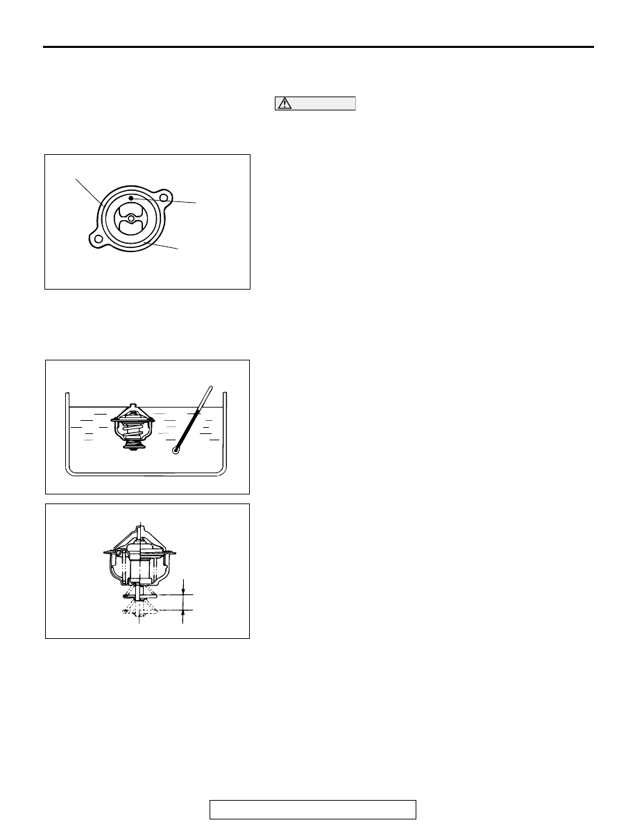
>>A<< THERMOSTAT INSTALLATION

CAUTION

Make absolutely sure that no oil adheres to the rubber ring 
of the thermostat. Also be careful not to fold or scratch the 
rubber ring during installation.
Install the thermostat so that the jiggle valve is facing straight 
up. Be careful not to fold or scratch the rubber ring.

INSPECTION

M1141002500267

Thermostat Check

1. Immerse the thermostat in water, and heat the water while 

stirring. Check the thermostat valve opening temperature.

Standard value: Valve opening temperature: 88 

± 1.5°

(190 

± 3°F)

2. Check that the amount of valve lift is at the standard value 

when the water is at the full-opening temperature.
NOTE: Measure the valve height when the thermostat is 
fully closed, and use this measurement to compare the 
valve height when the thermostat is fully open.

Standard value:

Full-opening temperature: 100

°C (212°F)

Amount of valve lift: 10 mm (0.39 inch)

AC004455

THERMOSTAT

JIGGLE

VALVE

RUBBER

RING

AB

ACX00400

ACX00401AB

VALVE LIFT

WATER PUMP

TSB Revision

ENGINE COOLING

14-12

WATER PUMP

REMOVAL AND INSTALLATION

M1141002700539

Pre-removal and Post-installation Operation
• Engine Coolant Draining and Refilling (Refer to GROUP 

00, Maintenance Servic

P.00-54

).

• Timing Belt Removal and Installation (Refer to GROUP 

11A, Timing Belt 

P.11A-34

).

AC004456

1

2

3

4

5

9

2

6

7

8

10

11

12

17 - 20 N·m

12 - 14 ft-lb

17 - 20 N·m

12 - 14 ft-lb

20 N·m

17 ft-lb

20 N·m

17 ft-lb

12 - 15 N·m

106 - 133 in-lb

AD

N

N

N

N

N

REMOVAL STEPS 

THERMOSTAT (REFER TO 

P.14-10

.)

<<A>> >>C<<

1.

RADIATOR UPPER HOSE 
CONNECTION

2.

WATER HOSE CONNECTION

3.

WATER OUTLET FITTING 
BRACKET

4.

WATER OUTLET FITTING 
ASSEMBLY

>>A<<

5.

O-RING

6.

GASKET

7.

THERMOSTAT CASE

8.

GASKET

9.

WATER PUMP BRACKET

>>B<<

10. WATER PUMP ASSEMBLY
11. GASKET

>>A<<

12. O-RING

REMOVAL STEPS  (Continued)

WATER PUMP

TSB Revision

ENGINE COOLING

14-13

REMOVAL SERVICE POINT

.

<<A>> RADIATOR UPPER HOSE DISCONNECTION
Make mating marks on the radiator hose and the hose clamp. 
Disconnect the radiator hose.

INSTALLATION SERVICE POINTS

.

>>A<< O-RING INSTALLATION

CAUTION

• Care must be taken not to permit engine oil or other 

grease to adhere to the O-ring.

• When inserting the pipe, check to be sure that there is 

no sand, dirt, etc. on its inner surface.

Rinse the mounting location of O-ring and water pipe with 
water, and install the O-ring and water pipe.

.

ACX01828

MATING MARKS

AB

ACX00402

O-RING

WATER PIPE

AD

WATER PUMP

TSB Revision

ENGINE COOLING

14-14

>>B<< WATER PUMP ASSEMBLY INSTALLATION

.

>>C<< RADIATOR UPPER HOSE CONNECTION
1. Insert each hose as far as the projection of the water outlet 

fitting.

2. Align the mating marks on the radiator hose and hose 

clamp, and then connect the radiator hose.

BOLT NO.

 DIAMETER (D) 

× LENGTH (L) mm (in)

1

× 14 (0.3 × 0.6)

2

× 20 (0.3 × 0.8)

3

× 25 (0.3 × 1.0)

4

× 65 (0.3 × 2.6)

AC004457AB

1

2

3

4

4

L

D

ACX01829AB

PROJECTION

WATER OUTLET
FITTING

MATING
MARKS


Content   ..  584  585  586  587   ..