Mitsubishi Montero Sport (2004+). Manual - part 513


  Index      Mitsubishi     Mitsubishi Montero Sport - service repair manual 2004 year


Search            


Content   ..  511  512  513  514   ..


Mitsubishi Montero Sport (2004+). Manual - part 513


IGNITION SWITCH

TSB Revision

CHASSIS ELECTRICAL

54-39

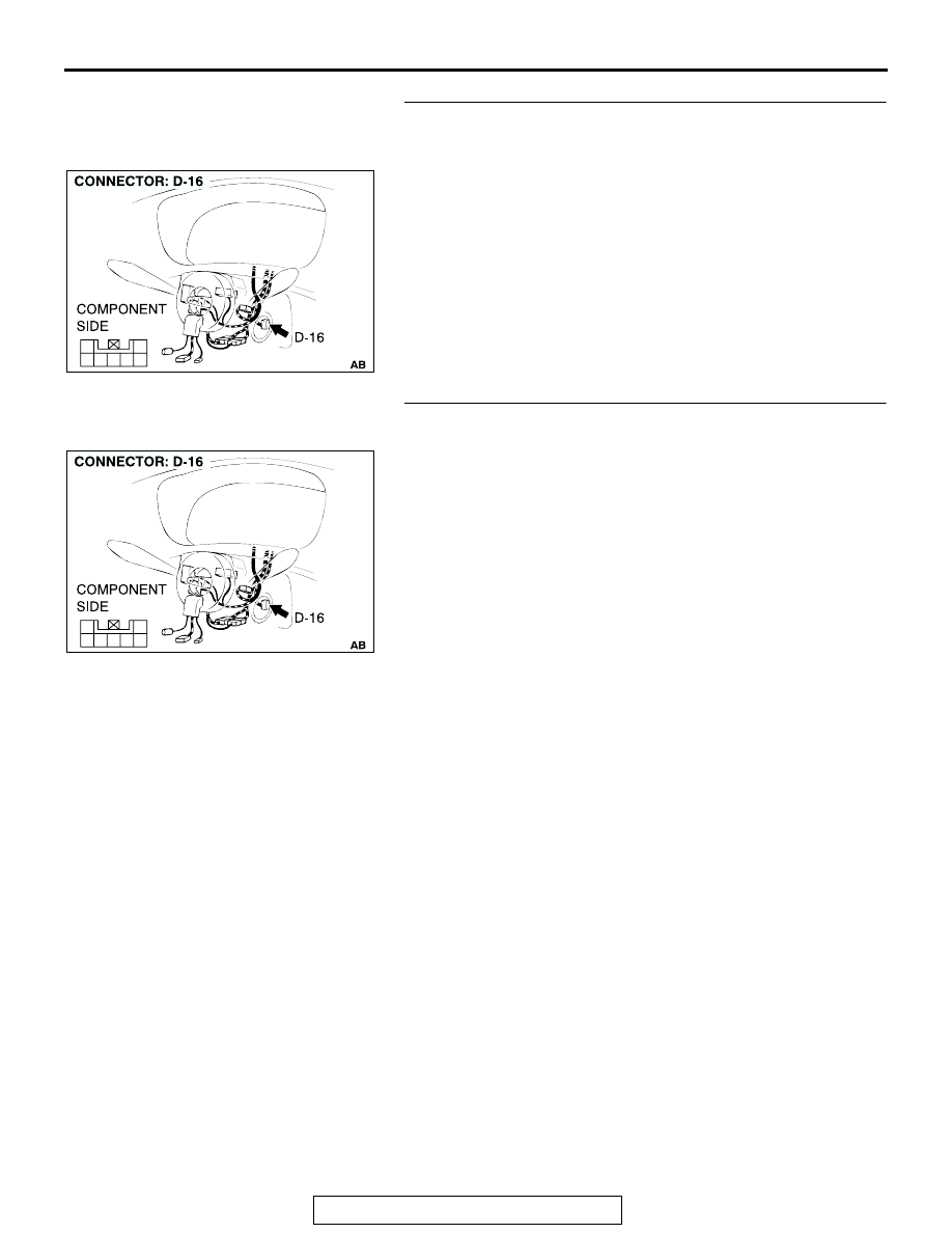
STEP 10. Check key reminder switch connector D-16 for 
loose, corroded or damaged terminals, or terminals 
pushed back in the connector.

Q: Is the key reminder switch connector D-16 in good 

condition?
YES : 
Go to Step 11.
NO :  Repair or replace it. Refer to GROUP 00E, Harness 

Connector Inspection 

P.00E-2

STEP 11. Check the harness wire between key reminder 
switch connector D-16 (terminal No.4) and body ground.

Q: Is the resistance wire between key reminder switch D-16 

and body ground in good condition?
YES : 
There is no action to be taken.
NO :  Repair or replace it. Refer to GROUP 00E, Harness 

Connector Inspection 

P.00E-2

AC202060

4

5

3

1

6

7

2

AC202060

4

5

3

1

6

7

2

IGNITION SWITCH

TSB Revision

CHASSIS ELECTRICAL

54-40

STEP 12. Check the harness wire between key reminder 
switch connector D-16 (terminal No.2 and 6) and 
ETACS-ECU connector D-11(terminal No.8 and 12).

NOTE: After checking intermediate connector C-72 and D-13, 
check the wires. If intermediate connector C-72 and D-13 are 
damaged, repair or replace them. Refer to GROUP 00E, Har-
ness Connector Inspection 

P.00E-2

.

Q: Is the harness wire between key reminder switch D-16 

and ETACS-ECU connector D-11 in good condition?
YES : 
Go to Step 13.
NO :  Repair or replace it. Refer to GROUP 00E, Harness 

Connector Inspection 

P.00E-2

.

1

2

4

5

3

6

8

9

7

10

11

13

14

12

16

17

201918

15

AC201086

AC202060

4

5

3

1

6

7

2

8

19

7

6

5

16

15

17 18

4

3

2

10 11 12 13

1
9

14

AC201910

CONNECTOR: C-72

AB

C-72 (B)

IGNITION SWITCH

TSB Revision

CHASSIS ELECTRICAL

54-41

STEP 13. Check for continuity between terminals (except 
No. 4 and No. 6) of key reminder switch connector D-16.

(1) Measure at key reminder switch connector D-16 without 

disconnecting the connector.

(2) Check that there is no continuity between key reminder 

switch terminal No. 4 and each terminal (except terminal 
No. 6), as well as between key reminder switch terminal 
No.6 and each terminal (except terminal No. 4).

Q: Does continuity exist between terminals?

YES : Replace the key reminder switch. If the functions, 

which are described in "CIRCUIT OPERATION", work 
normally, the input signal from the key reminder 
switch should be normal.

NO :  Go to Step 14.

STEP 14. Recheck for malfunction.
Q: Is a malfunction eliminated?

YES : The procedure is complete. (If no malfunctions are 

found in all steps, an intermittent malfunction is 
suspected. Refer to GROUP 00, How to Use 
Troubleshooting/Inspection Service Point 

P.00-7

.

NO :  Go to Step 1.

AC202060

4

5

3

1

6

7

2

IGNITION SWITCH

TSB Revision

CHASSIS ELECTRICAL

54-42

EQUIPMENT DIAGNOSIS

IMMOBILIZER SYSTEM DIAGNOSIS

M1543009901393

INTRODUCTION TO IMMOBILIZER 
SYSTEM DIAGNOSIS

CAUTION

The encrypted code should always be re-regis-
tered when replacing the immobilizer-ECU.
The immobilizer system consists of the immobi-
lizer-ECU, powertrain control module, ignition key 
and ignition key ring antenna. If the engine cannot be 
started by using a registered ignition key, one of 
these components may be defective. In addition, if 

the immobilizer system has immobilized the engine, 
MFI system DTC P1610 will be output. In this case, 
observe the immobilizer system troubleshooting. 
Then, if a malfunction is resolved, the MFI system 
DTC P1610 should not reset.

IMMOBILIZER SYSTEM DIAGNOSTIC TROUBLESHOOTING STRATEGY

M1543006900711

Use these steps to plan your diagnostic strategy. If 
you follow them carefully, you will be sure that you 
have exhausted most of the possible ways to find an 
immobilizer system fault.
1. Gather information about the problem from the 

customer.

2. Verify that the condition described by the 

customer exists.

3. Check the vehicle for any immobilizer system 

DTC.

4. If you cannot verify the condition and there are no 

immobilizer system DTCs, the malfunction is 
intermittent. Refer to GROUP 00, How to Use 
Troubleshooting/inspection Service Points - How 
to Cope with Intermittent Malfunctions 

P.00-7

.

5. If you can verify the condition but there are no 

immobilizer system DTCs, or the system cannot 
communicate with scan tool MB991958, refer to 
Symptom Chart and find the faul

P.54-48

.

6. If there is an immobilizer system DTC, record the 

number of the DTC, then erase the DTC from the 
memory using scan tool MBB991958.

7. Recreate the immobilizer system DTC set 

conditions to see if the same immobilizer system 
DTC will set again.
(1) If the same immobilize system DTC sets 

again, perform the diagnostic procedures for 
the DTC. Refer to Diagnostic Trouble Code 
Char

P.54-43

.

(2) If you cannot get the same immobilizer system 

DTC to set again, the malfunction is 
intermittent. Refer to GROUP 00, How to Use 
Troubleshooting/inspection Service Points 

− 

How to Cope with Intermittent Malfunctions 

P.00-7

.


Content   ..  511  512  513  514   ..