Mitsubishi Montero Sport (2004+). Manual - part 495


  Index      Mitsubishi     Mitsubishi Montero Sport - service repair manual 2004 year


Search            


Content   ..  493  494  495  496   ..


Mitsubishi Montero Sport (2004+). Manual - part 495


COMPASS AND TEMPERATURE DISPLAY DIAGNOSIS

TSB Revision

INTERIOR

52A-25

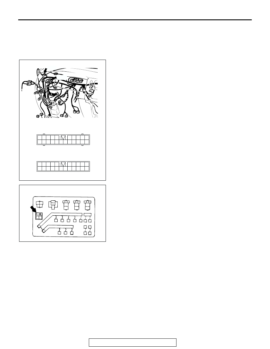
NOTE: After inspecting intermediate connector C-01 and C-41, 
junction block connectors D-06, D-08 and IOD or storage con-
nector A-54X, inspect the wire. If intermediate connector C-01 
and C-41, junction block connectors D-06, D-08, and IOD or 
storage connector A-54X are damaged, repair or replace them. 
Refer to GROUP 00E, Harness Connector Inspection 

P.00E-2

.

AC201076

22

9 10

20

19

6 7 8

21

17

1516

5

14

1213

3

2

4

18

11

1

22

2021

10

9

8

1718

6 7

19

1415

4 5

1112

1 2 3

13

16

CONNECTORS: C-01, C-41

C-01

C-41

AB

C-01

C-41

AC201082

1 2

AB

A-54X

RELAY BOX IN ENGINE COMPARTMENT

CONNECTOR: A-54X

COMPASS AND TEMPERATURE DISPLAY DIAGNOSIS

TSB Revision

INTERIOR

52A-26

Q: Is the harness wires between inside rear view mirror 

(with compass and temperature display) connector E-59 
(terminal No.1) and ignition switch (ACC) in good 
condition?
YES : 
Go to Step 6.
NO :  Repair them. Then go to Step 6.

STEP 4. Measure the resistance at the inside rear view 
mirror (with compass and temperature display) ground 
circuit.

(1) Remove the inside rear view mirror (with compass and 

temperature display) (Refer to 

P.52A-43

.)

(2) Disconnect the connector.
(3) Check at inside rear view mirror (with compass and 

temperature display) harness side connector (front side) 
E-59.

(4) Measure the resistance between terminal number 3 and 

body ground.

• Resistance should be 2 ohms or less

Q: Does the measured resistance value correspond with 

this range?
YES : 
Go to Step 6.
NO :  Go to Step 5.

AC201088

1

2

3

4

5

7 6

16151413121110 9 8

1

2

3

4

CONNECTOR: D-06, D-08

JUNCTION BLOCK 
(FRONT SIDE)

JUNCTION BLOCK
 (REAR SIDE)

COMPONENT SIDE

AB

D-06

D-08

COMPONENT SIDE

AC201078

4

5

3

1

6

7

2

CONNECTOR: E-59

COMPONENT 
SIDE

AB

E-59

AC003749 AB

HARNESS SIDE
CONNECTOR
(FRONT SIDE) E-59

COMPASS AND TEMPERATURE DISPLAY DIAGNOSIS

TSB Revision

INTERIOR

52A-27

STEP 5. Check the harness wires between inside rear view 
mirror (with compass and temperature display) E-59 
(terminal No.3) and body ground.

NOTE: After inspecting intermediate connectors C-01, inspect 
the wire. If intermediate connectors C-01 is damaged, repair 
the wire. If intermediate connectors C-01 is damaged, repair or 
replace it. Refer to GROUP 00E, Harness connector inspection 

P.00E-2

Q: Is the harness wires between inside rear view mirror 

(with compass and temperature display) connector E-59 
(terminal No.3) and body ground in good condition?
YES : 
Replace the inside rear view mirror (with compass 

and temperature display) (Refer to 

P.52A-43

). Then 

go to Step 6.

NO :  Repair them. Then go to Step 6.

STEP 6. Check the symptoms.
Q: Does the outside temperature meter and electronic 

compass display values normally?
YES : 
There is no action to be taken.
NO :  This procedure is complete. (If no malfunctions are 

found in all steps, an intermittent malfunction is 
suspected. Refer to GROUP 00, How to Use 
Troubleshooting/Inspection Service Points 

− How to 

Cope with Intermittent Malfunction 

P.00-7

.) 

AC201078

4

5

3

1

6

7

2

CONNECTOR: E-59

COMPONENT 
SIDE

AB

E-59

AC201079

22

9 10

20

19

6 7 8

21

17

1516

5

14

1213

3

2

4

18

11

1

CONNECTOR: C-01

AB

C-01

COMPASS AND TEMPERATURE DISPLAY DIAGNOSIS

TSB Revision

INTERIOR

52A-28

INSPECTION PROCEDURE 2: The Advance Direction is Devited.

.

CIRCUIT OPERATION
Refer to Outside Temperature Meter and Electronic 
Compass Circuit (Refer to 

P.52A-21

.) The vehicle 

direction is displayed by the output of the geomag-
netic sensor built into the outside temperature meter 
and electronic compass.

.

TECHNICAL DESCRIPTION (COMMENT)
The vehicle magnetism tends to be disturbed particu-
larly at such places as tunnel, railway crossing, area 
along railway, elevated road, urban area crowded 
with high-storied buildings, area above subway, etc. 
If disturbed, the driving direction marker will fluctu-
ate.

.

TROUBLESHOOTING HINTS
The calibration of the compass or compass variance 
failed.

DIAGNOSIS

The calibration of the compass or compass variance (Refer to  

P.52A-32

P.52A-33

.)

INSPECTION PROCEDURE 3: The Compass Cannot be Calibrated.

.

CIRCUIT OPERATION
Refer to Outside Temperature Meter and Electronic 
Compass Circuit (Refer to 

P.52A-21

.)

.

TECHNICAL DESCRIPTION (COMMENT)
The inside rear view mirror (with compass and tem-
perature display) may be defective.

.

TROUBLE SHOOTING HINTS
Malfunction of the inside rear view mirror (with com-
pass and temperature display).

DIAGNOSIS

Check that the calibration of the compass can be carried out at 
another place.

1. Move the vehicle to be checked to another place.

NOTE: Move to a wide flat place where calibration of the 
compass can be carried out.

2. Check again that calibration of the compass can be carried 

out. 
NOTE: If the calibration is correct, the following causes can 
be assumed.

• Calibration is difficult due to the magnet direction and 

direction of the vehicle at the start of calibration.

• There is a disturbing magnetic field in the area, and cali-

bration is difficult.

If the calibration is correct, check that the malfunction is elimi-
nated.
If the calibration is incorrect, replace the inside rear view mirror 
(with compass and temperature display) (Refer to 

P.52A-43

.) 

Then, check that the malfunction is eliminated.


Content   ..  493  494  495  496   ..