Mitsubishi Montero Sport (2004+). Manual - part 493


  Index      Mitsubishi     Mitsubishi Montero Sport - service repair manual 2004 year


Search            


Content   ..  491  492  493  494   ..


Mitsubishi Montero Sport (2004+). Manual - part 493


SEAT BELT DIAGNOSIS

TSB Revision

INTERIOR

52A-17

.

CIRCUIT OPERATION

• The voltage from the ignition switch circuit flashes 

the seat belt warning light.

• The system flashes the seat belt warning light for 

6 seconds after the ignition switch is turned "ON," 
and sounds the seat belt tone alarm if the seat 
belt is not fastened.

.

TECHNICAL DESCRIPTION (COMMENT)
There may be a malfunction of the seat belt warning 
light circuit or ETACS-ECU.

.

TROUBLESHOOTING HINTS

• Malfunction of the seat belt warning light bulb

• Malfunction of the ETACS-ECU

• Damaged wiring harnesses or connectors
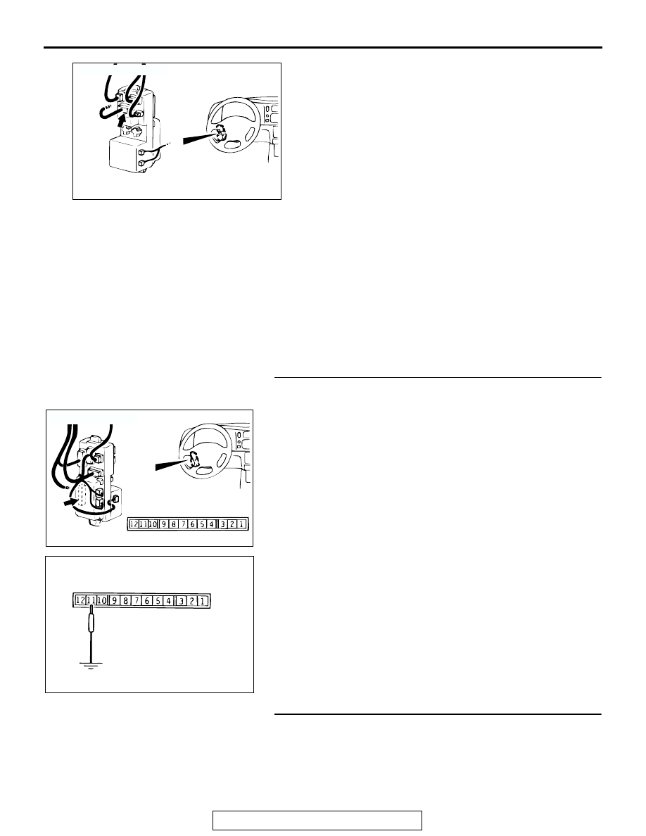
DIAGNOSIS

STEP 1. Check the seat belt warning light circuit line at 
junction block connector D-11.

(1) Remove the ETACS-ECU and measure at the junction 

block side.

(2) Turn the ignition switch "ON."

(3) Connect terminal 11 to the ground.

The system is normal if the seat belt warning light 

illuminates.

(4) Turn the ignition switch "OFF."
Q: Does the warning light illuminate?

YES : Replace the ETACS-ECU 

P.52A-52

. Then go to Step 

4  .

NO :  Go to Step 2.

STEP 2. Check the seat belt warning light bulb.
Q: Is the seat belt warning light bulb normal?

YES : Go to Step 3.
NO :  Replace the seat belt warning light bulb. Then go to 

Step 4.

AC003242AC

JUNCTION
BLOCK (FRONT)

CONNECTOR: D-06

D-06

AC201084

JUNCTION 
BLOCK (REAR)

D-11

COMPONENT SIDE

AB

CONNECTOR: D-11

AC003243

D-11
(JUNCTION BLOCKSIDE)

AB

SEAT BELT DIAGNOSIS

TSB Revision

INTERIOR

52A-18

STEP 3. Check the harness wires between the ignition 
switch (IG1) and junction block connector D-11(terminal 
No 3).

NOTE: Check the intermediate connectors C-02, C-04, D-06, 
D-08, D-13, and then their wiring harness. If the intermediate 
connectors C-02, C-04, D-06, D-08, D-13 are damaged, repair 
or replace it. Refer to GROUP 00E, Harness Connector Inspec-
tion 

P.00E-2

. Then go to Step 4.

Q: Is the harness wire between the ignition switch (IG

1

and junction block connector D-11 (terminal No.3) in 
good condition?
YES : 
Go to Step 4.
NO :  Repair them. Then go to Step 4.

AC201087

1

2

3

4

5

7 6

16151413121110 9 8

1

2

3

4

1

2

4

5

3

6

8

9

7

10

11

13

14

12

16

17

201918

15

CONNECTORS: D-06, D-08, D-11, D-13

JUNCTION 
BLOCK (FRONT)

JUNCTION 
BLOCK (REAR)

D-06

D-13

D-08

D-11

D-06 COMPONENT  SIDE

D-08 COMPONENT  SIDE

D-11 COMPONENT  SIDE

D-13 COMPONENT  SIDE

AB

AC201074

51

52

55 54 53

56

58

59

57

60

61

62

21

23

24

27 26 25

22

28

30

31

29

32

AB

CONNECTORS: C-02, C-04

C-02 (B) C-04

C-04 COMPONENT SIDE

C-02 COMPONENT SIDE

SEAT BELT DIAGNOSIS

TSB Revision

INTERIOR

52A-19

STEP 4. Retest the system.
Q: The seat belt tone alarm sound, but does the seat belt 

warning light illuminate or flash?
YES : 
This procedure is complete. (If no malfunctions are 

found in all steps, an intermittent malfunction is 
suspected. Refer to GROUP 00, How to Use 
Troubleshooting/Inspection Service Points 

− How to 

Cope with Intermittent Malfunction 

P.00-7

.) 

NO :  There is no action to be taken.

COMPASS AND TEMPERATURE DISPLAY DIAGNOSIS

TSB Revision

INTERIOR

52A-20

COMPASS AND TEMPERATURE DISPLAY DIAGNOSIS

INTRODUCTION TO COMPASS AND TEMPERATURE DISPLAY DIAGNOSIS

M1521004200075

If the compass and temperature do not function, 
there may be trouble in the electrical system, or the 
calibration of the compass may be faulty.

M1524003100267

COMPASS AND TEMPERATURE DISPLAY DIAGNOSTIC TROUBLESHOOTING 
STRATEGY

Use these steps to plan your diagnostic strategy. If 
you follow them carefully, you will be sure that you 
have exhausted most of the possible ways to find a 
inside rear view mirror with compass and tempera-
ture display fault.

1. Gather information from the customer.

2. Verify that the condition described by the cus-

tomer exists.

3. Find the malfunction by following the Symptom 

Chart.

4. Verify malfunction is eliminated.

SYMPTOM CHART

M1521003500136

SYMPTOM

INSPECTION 
PROCEDURE 
NO.

REFERENCE 
PAGE

There is no display.

1

P.52A-21

The advance direction is deviated.

2

P.52A-28

The compass cannot be calibrated.

3

P.52A-28

There is a discrepancy between the actual out side temperature and 
displayed temperature or an error displays (CS, OS).

4

P.52A-29


Content   ..  491  492  493  494   ..