Mitsubishi Montero Sport (2004+). Manual - part 474


  Index      Mitsubishi     Mitsubishi Montero Sport - service repair manual 2004 year


Search            


Content   ..  472  473  474  475   ..


Mitsubishi Montero Sport (2004+). Manual - part 474


LIFTGATE

TSB Revision

BODY

42-151

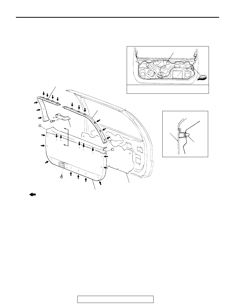
LIFTGATE TRIM AND WATERPROOF FILM

REMOVAL AND INSTALLATION

M1424001400094

AC003802

A

A

SECTION A – A

ADHESIVE: 
        3M™ AAD PART NO. 8625 OR EQUIVALENT

1

2

3

4

5

4

5

CLIP

NOTE  
       : Resin clip position

AB

 REMOVAL STEPS

1. COVER <VEHICLES WITH 

HIGH-MOUNTED STOPLIGHT>

2. LIFTGATE UPPER TRIM <LH>

3. LIFTGATE UPPER TRIM <RH>
4. LIFTGATE LOWER TRIM
5. WATERPROOF FILM

 REMOVAL STEPS (Continued)

LIFTGATE

TSB Revision

BODY

42-152

LIFTGATE HANDLE AND LATCH

REMOVAL AND INSTALLATION

M1424001700095

Pre-removal Operation
• Liftgate Garnish Removal (Refer to GROUP 51, Grill, 

Molding and Garnish 

P.51-6

.)

• Liftgate Trim and Waterproof Film Removal (Refer to 

P.42-151

.)

Post-installation Operation
• Liftgate Handle Play Inspection (Refer to 

P.42-148

.)

• Liftgate Trim and Waterproof Film Installation (Refer to 

P.42-151

.)

• Liftgate Garnish Installation (Refer to GROUP 51, Grill, 

Molding and Garnish 

P.51-6

.)

AC003803

1

2

3

4

5

6

1

6

AB

9 N·m
80 in-lb

LIFTGATE LOCK KEY CYLINDER 
REMOVAL STEPS
1. LIFTGATE HANDLE
2. CYLINDER LOCK RETAINER
3. LIFTGATE LOCK KEY CYLINDER

LIFTGATE LATCH REMOVAL STEPS
4. LIFTGATE LOCK ACTUATOR
5. HOLDER
6. LIFTGATE LATCH ASSEMBLY

LIFTGATE

TSB Revision

BODY

42-153

INSPECTION

M1424001200108

LIFTGATE LOCK ACTUATOR CHECK

Actuator Operation Check

Actuator Switch Check <Vehicles with keyless entry sys-
tem>

LIFTGATE LOCK KEY CYLINDER SWITCH CHECK

LEVER 
POSITION

BATTERY 
CONNECTION

LEVER 
OPERATION

At the "LOCK" 
position

• Connect terminal 

No. 1 to the 
positive battery 
terminal

• Connect terminal 

No. 2 to the 
negative battery 
terminal

The lever moves 
from the "LOCK" 
position to the 
"UNLOCK" 
position.

At the "UNLOCK" 
position

• Connect terminal 

No. 2 to the 
positive battery 
terminal

• Connect terminal 

No. 1 to the 
negative battery 
terminal

The lever moves 
from the 
"UNLOCK" 
position to the 
"LOCK" position.

SWITCH 
POSITION

TESTER 
CONNECTION

SPECIFIED 
CONDITION

At the "LOCK" 
position

− 5

Less than 2 ohms

At the "UNLOCK" 
position

− 5

Less than 2 ohms

5

4

3

2

1

AC003805AB

UNLOCK

LOCK

A

VIEW A 

SWITCH 
POSITION

TESTER 
CONNECTION

SPECIFIED 
CONDITION

At the "LOCK" 
position

− 2

Less than 2 ohms

NEUTRAL (OFF)

− 2

− 3

Open circuit 

At the "UNLOCK" 
position

− 3

Less than 2 ohms

3

2

1

AC003804

KEYLESS ENTRY SYSTEM

TSB Revision

BODY

42-154

KEYLESS ENTRY SYSTEM

GENERAL INFORMATION

M1428000100315

Some models are equipped with a keyless entry sys-

tem. The main features are:

• The antenna is incorporated in the keyless entry 

receiver-ECU.

• ID code can be registered by using the scan tool 

MB991958 (MUT-III sub assembly).

• Transmitter is a key holder type, which incorpo-

rates lock switch, unlock switch, and panic 

switch.

• The locking is answered back by two times' flash-

ing of the doom light, two times' flashing of the 

turn signal lights and one time sounding of the 

horn answerback.

• The unlocking is answered back by illuminating of 

the doom light for 15 seconds and one time flash-

ing of the turn signal lights.

KEYLESS ENTRY SYSTEM DIAGNOSIS

INTRODUCTION TO KEYLESS ENTRY SYSTEM DIAGNOSIS

M1428002600037

A signal is transmitted from the transmitter to the 
keyless entry receiver-ECU. If the signal corre-
sponds with that stored in the keyless entry 
receiver-ECU, the ECU send a signal to the 
ETACS-ECU. Then the door lock/unlock control is 
operated. When doors are locked, the dome light, the 
cargo space light and hazard warning lights will flash 
twice when doors are unlock, the dome light, the 
cargo space light will come on and dim after 15 sec-
onds, and the hazard warning lights flash once.

If the following type of symptom occurs, there may 
be a fault.

• All the doors cannot be locked or unlocked when 

the transmitter is operated.

• The secret code cannot de registered.

• The dome light, the cargo space light and the 

hazard warning lights do not operate through the 
answerback function.

KEYLESS ENTRY SYSTEM DIAGNOSTIC TROUBLESHOOTING STRATEGY

M1428001500037

Use these steps to plan your diagnostic strategy. If 
you follow them carefully, you will be sure that you 
have exhausted most of the possible ways to find a 
keyless entry system fault.
1. Gather information from customer.

2. Verify that the condition described by the 

customer exists.

3. Find the malfunction by following the Symptom 

Chart.

4. Verify that the malfunction is eliminated.

SYMPTOM CHART

M1428001800050

SYMPTOM

INSPECTION 
PROCEDURE

REFERENCE PAGE

Communication with scan tool 
is not possible.

Communication with all system 
is not possible.

Refer to GROUP 13A, 
Symptom Procedure 

P.13A-716

The ETACS-ECU input signal 
can not be detected by the 
scan tool.

P.42-23

All of the doors can not be locked or unlocked using the 
transmitter. (However, the central door lock system operates 
normally.)

1

P.42-155

The secret code cannot be registered.

2

P.42-157

The dome light, the cargo space light and the hazard warning 
lights do not operate through the answerback function. 
(However, the dome light, the cargo space light and the hazard 
warning lights operates normally.)

3

P.42-158

The horn do not operate through the answerback function.

Refer to GROUP 54 

P.54-176


Content   ..  472  473  474  475   ..