Mitsubishi Montero Sport (2004+). Manual - part 472


  Index      Mitsubishi     Mitsubishi Montero Sport - service repair manual 2004 year


Search            


Content   ..  470  471  472  473   ..


Mitsubishi Montero Sport (2004+). Manual - part 472


DOOR

TSB Revision

BODY

42-143

Actuator Switch Continuity Check <Right side 

 Vehicles 

with keyless entry system only>

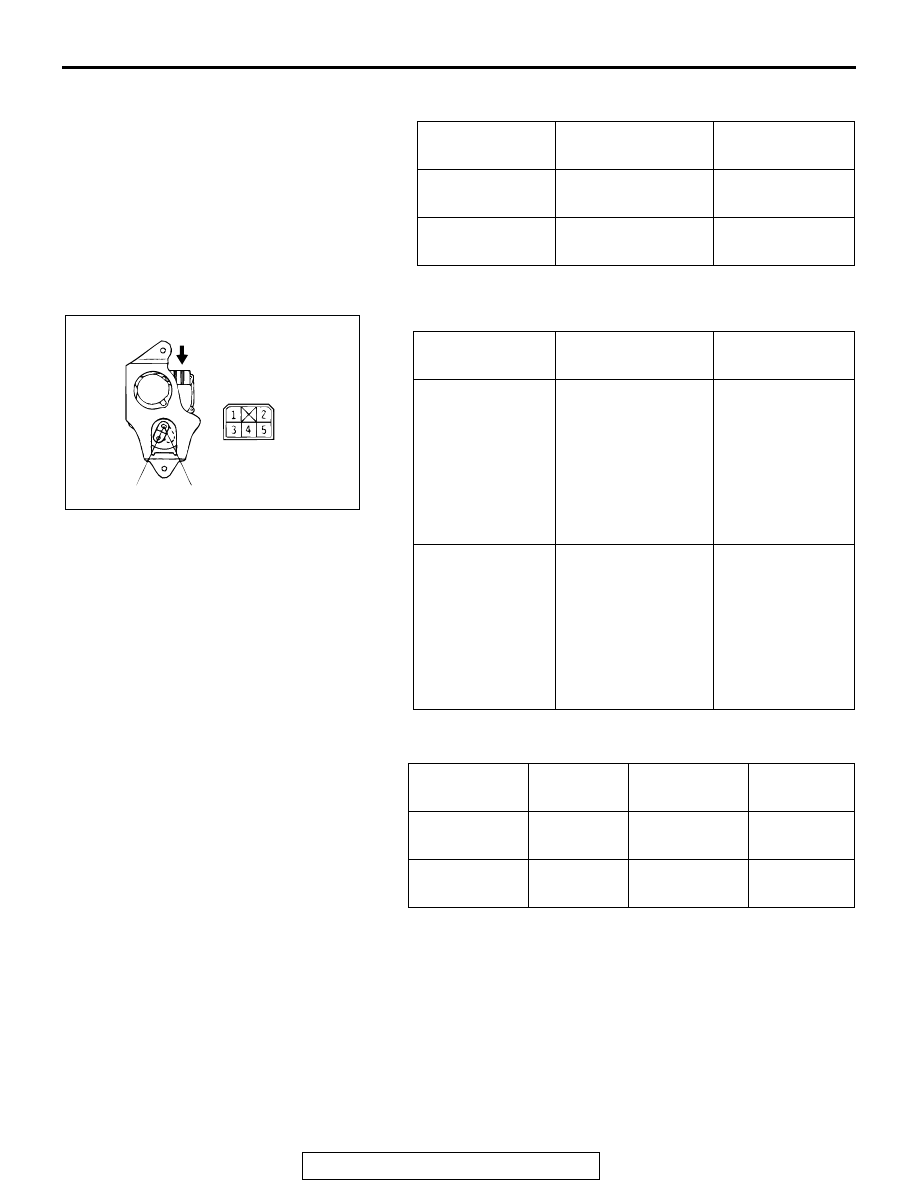
REAR DOOR LOCK ACTUATOR CHECK

Actuator Operation Check 

Actuator Switch Continuity Check <Vehicles with keyless 
entry system>

SWITCH 
POSITION

TESTER 
CONNECTION

SPECIFIED 
CONDITION

At the LOCK 
position

− 3

Less than 2 ohms

At the UNLOCK 
position

− 3

Less than 2 ohms

LEVER 
POSITION

BATTERY 
CONNECTION

LEVER 
OPERATION

At the "B" position

• Connect terminal 

No. 1 and the 
positive battery 
terminal.

• Connect terminal 

No. 2 and the 
negative battery 
terminal.

The lever moves 
from the "B" 
position to the "C" 
position.

At the "C" position

• Connect terminal 

No. 2 and the 
positive battery 
terminal.

• Connect terminal 

No. 1 and the 
negative battery 
terminal.

The lever moves 
from the "C" 
position to the "B" 
position.

ACTUATOR

SWITCH 
POSITION

TESTER 
CONNECTION

SPECIFIED 
CONDITION

LH side

At the C 
position

− 4

Less than 2 
ohms

RH side

At the B 
position

− 5

Less than 2 
ohms

AC003792AB

A

VIEW A

B

C

DOOR

TSB Revision

BODY

42-144

DOOR LOCK KEY CYLINDER SWITCH 
CONTINUITY CHECK

<DRIVER'S SIDE>

<PASSENGER'S SIDE>

CENTER DOOR LOCK SWITCH CONTINUITY 
CHECK

Remove the power window switch. (Refer to 

P.42-134

.)

Driver's side

Passenger's side

SWITCH 
POSITION

TESTER 
CONNECTION

SPECIFIED 
CONDITION

At the LOCK 
position

− 3

Less than 2 ohms

At the NEUTRAL 
(OFF) position

− 2

− 3

Open circuit 

At the UNLOCK 
position

− 2

Less than 2 ohms

SWITCH 
POSITION

TESTER 
CONNECTION

SPECIFIED 
CONDITION

At the LOCK 
position

− 3

Less than 2 ohms

At NEUTRAL 
(OFF) position

− 2

− 3

Open circuit 

At the UNLOCK 
position

− 2

Less than 2 ohms 

AC003793

SWITCH 
POSITION

TESTER 
CONNECTION

SPECIFIED 
CONDITION

At the LOCK 
position

− 12

Less than 2 ohms

At the OFF 
position

− 12

10 

− 12

Open circuit 

At the UNLOCK 
position

10 

− 12

Less than 2 ohms

SWITCH 
POSITION

TESTER 
CONNECTION

SPECIFIED 
CONDITION

At the LOCK 
position

− 2

Less than 2 ohms

At the OFF 
position

− 2

− 3

Open circuit 

At the UNLOCK 
position

− 3

Less than 2 ohms

AC003993

5

4

6

13

3

2

1

14

12

11

10

9

8

7

DOOR LOCK SWITCH

AB

5

4

6

3

2

1

8

7

AC003994

DOOR LOCK 

SWITCH

AB

DOOR

TSB Revision

BODY

42-145

WINDOW GLASS RUNCHANNEL AND DOOR OPENING WEATHERSTRIP

REMOVAL AND INSTALLATION 

M1423003100364

REMOVAL SERVICE POINT

.

<<A>> DOOR OUTER OPENING WEATHERSTRIP 
REMOVAL
Make a tool as shown and remove the door opening weather-
strip.

AC003794

1

2

3

4

5

6

1

3

4

6

2

5

AB

FRONT DOOR

REAR DOOR

DOOR INNER OPENING 
WEATHERSTRIP REMOVAL STEPS
• FRONT SCUFF PLATE, REAR 

SCUFF PLATE, CENTER PILLAR 
LOWER TRIM AND COWL SIDE 
TRIM (REFER TO GROUP 52A, 
TRIMS 

P.52A-41

.)

1. DOOR INNER OPENING 

WEATHERSTRIP

DOOR OUTER OPENING 
WEATHERSTRIP REMOVAL 
2. SPRING PIN

<<A>> >>A<<

3. DOOR OUTER OPENING 

WEATHERSTRIP

DOOR WINDOW GLASS 
RUNCHANNEL REMOVAL STEPS
4. DOOR WINDOW GLASS 

RUNCHANNEL

DOOR BELTLINE INNER 
WEATHERSTRIP REMOVAL STEPS
• DOOR TRIM (REFER TO 

P.42-134

.)

5. DOOR BELTLINE INNER 

WEATHERSTRIP

DOOR BELTLINE INNER 
WEATHERSTRIP REMOVAL STEPS
• DOOR MIRROR (REFER TO 

GROUP 51, DOOR MIRROR 

P.51-26

.)

6. DOOR BELTLINE OUTER 

WEATHERSTRIP

ACX00555

15 mm (0.6 in)

8 mm 
(0.3 in)

AB

4 mm (0.2 in)

THICKNESS:
1 mm (0.04 in)

FABRICATED TOOL

LIFTGATE

TSB Revision

BODY

42-146

INSTALLATION SERVICE POINT

.

>>A<< DOOR OUTER OPENING WEATHERSTRIP INSTAL-
LATION
The clip color identifies the left and right weatherstrips, so be 
sure to use the colors so as to install correctly.

LIFTGATE

LIFTGATE DIAGNOSIS

INTRODUCTION TO LIFTGATE DIAGNOSIS

M1424002500094

Refer to 

P.42-93

.

LIFTGATE DIAGNOSTIC TROUBLESHOOTING STRATEGY

M1424002600091

Use these steps to plan your diagnostic strategy. If 
you follow them carefully, you will be sure that you 
have exhausted most of the possible ways to find a 
liftgate fault.
1. Gather information from the customer.

2. Verify that the condition described by the 

customer exists.

3. Find the malfunction by following the Symptom 

Chart.

4. Verify that the malfunction is eliminated.

SYMPTOM CHART

M1424002700106

SYMPTOM PROCEDURES

INSPECTION PROCEDURE 1: Liftgate Hard to Open

DIAGNOSIS

STEP 1. Adjust the latch and striker engagement.
(Refer to 

P.42-148

.)

Q: Is the latch and striker engagement adjusted?

YES : 

Go to Step 2.

NO : 

Adjust lift gate. (Refer to 

P.42-148

.) Then go 

to Step 4.

STEP 2. Check for possible lock rod damage.

Q: Is the possible lock rod damaged?

YES : 

Repair or replace possible lock rod, then go 

to Step 4.

NO : 

Go to Step 3.

APPLICABLE SIDE

IDENTIFICATION COLOR

Left door

Brown or yellow

Right door

Natural (White)

SYMPTOM

INSPECTION 
PROCEDURE

REFERENCE PAGE

Liftgate hard to open

1

P.42-124

Liftgate does not open or close completely.

2

P.42-125

Uneven gap between body

3

P.42-125


Content   ..  470  471  472  473   ..