Mitsubishi Montero Sport (2004+). Manual - part 454


  Index      Mitsubishi     Mitsubishi Montero Sport - service repair manual 2004 year


Search            


Content   ..  452  453  454  455   ..


Mitsubishi Montero Sport (2004+). Manual - part 454


DOOR

TSB Revision

BODY

42-71

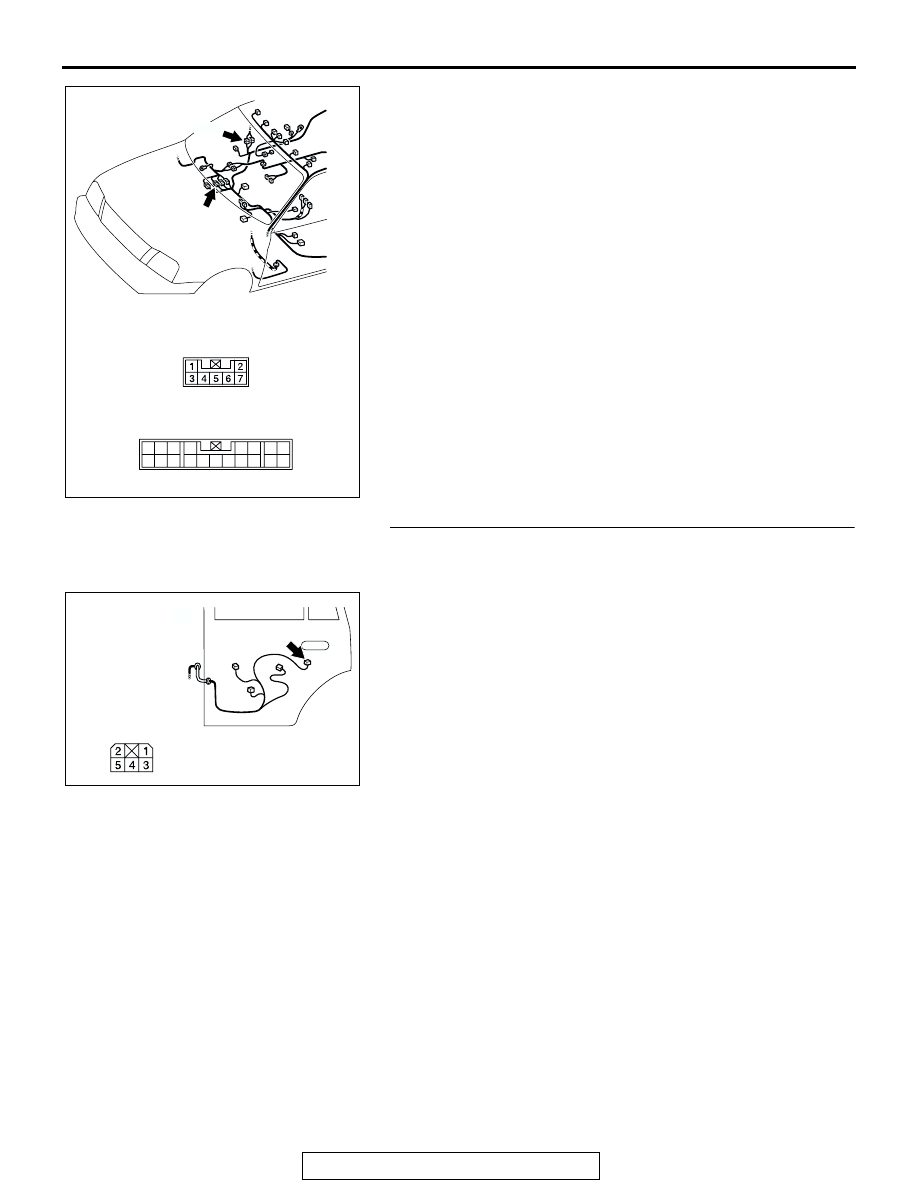
NOTE: After inspecting intermediate connectors E-01 and E-42 
inspect the wire. If intermediate connectors E-01 or E-42 is 
damaged, repair or replace damaged component. Refer to 
GROUP 00E 

P.00E-2

, Harness Connector Inspection. Then go 

to Step 22.
Q: Are there any damaged harness wires between 

ETACS-ECU connectors D-10 (terminals No.21 and 
No.24) <Vehicles without keyless entry system> or D-27 
(terminals No.41 and No.42) <Vehicles with keyless 
entry system> and door lock actuator (reart: RH) 
connector F-21 (terminals No.1 and No.2)?
YES : 
Replace the ETACS-ECU and then go to Step 22.
NO :  Repair or replace the damaged components. Refer to 

GROUP 00E 

P.00E-2

, Harness Connector inspection. 

Then go to Step22.

STEP 14. Check door lock actuator (rear: LH) connector 
F-09 for loose, corroded or damaged terminals, or 
terminals pushed back in the connector.
Q: Is the connector in good condition?

YES : Go to step 15.
NO :  Repair or replace the damaged components. Refer to 

GROUP 00E 

P.00E-2

, Harness Connector inspection. 

Then go to Step 22.

AC309311

CONNECTORS: E-01, E-42

E-42

E-01 

AD

E-01

E-42

8

19

7

6

5

16

15

17 18

4

3

2

10 11 12 13

1
9

14

AC309454

CONNECTOR: F-09

F-09

REAR DOOR <LH>

AB

COMPONENT SIDE

DOOR

TSB Revision

BODY

42-72

STEP 15. Check the rear door lock actuator (rear: LH).
(1) Remove the door latch assembly (Refer to 

P.42-140

).

(2) Follow the table to check the rear door lock actuator 

(lock/unlock).
Actuator Operation Check 

Q: Is the rear door lock actuator damaged?

YES : Replace the door lock actuator assembly (rear: LH), 

go to Step 22.

NO :  Go to Step 16.

LEVER 
POSITION

BATTERY 
CONNECTION

LEVER 
OPERATION

At the "B" position

• Connect terminal 

No. 1 and the 
positive battery  
terminal.

• Connect terminal 

No. 2 and the 
negative battery  
terminal.

The lever moves 
from the "B" 
position to the "C" 
position.

At the "C" position

• Connect terminal 

No. 2 and the 
positive battery  
terminal.

• Connect terminal 

No. 1 and the 
negative battery  
terminal.

The lever moves 
from the "C" 
position to the "B" 
position.

AC003792AB

A

VIEW A

B

C

DOOR

TSB Revision

BODY

42-73

STEP 16. Check ETACS-ECU connectors D-10 <Vehicles 
without keyless entry system> and D-27 <Vehicles with 
keyless entry system> for loose, corroded or damaged 
terminals, or terminals pushed back in the connector.
Q: Are ETACS-ECU connectors D-10 <Vehicles without 

keyless entry system> and D-27 <Vehicles with keyless 
entry systerm> in good condition?
YES : 
Go to Step 17.
NO :  Repair or replace the damaged components. Refer to 

GROUP 00E 

P.00E-2

, Harness Connector inspection. 

Then go to Step 22.

AC202002

6 5 4

1

2

7

3
8

41

43

51

42

50

44

52

46 45

53

49

47

30

48

56

55

D-27 (B)

D-10

JUNCTION 
BLOCK (REAR)

CONNECTORS: D-10, D-27

AB

D-27 COMPONENT  SIDE

D-10 COMPONENT SIDE

21

22

23

24

25

26

27

28

DOOR

TSB Revision

BODY

42-74

STEP 17. Check the harness wire between ETACS-ECU 
connectors D-10 (terminals No.21 and No.24) <Vehicles 
without keyless entry system> or D-27 (terminals No.41 
and No.42) <Vehicles with keyless entry system> and door 
lock actuator (rear: LH) connector F-09 (terminals No.1 and 
No.2).

AC202002

6 5 4

1

2

7

3
8

41

43

51

42

50

44

52

46 45

53

49

47

30

48

56

55

D-27 (B)

D-10

JUNCTION 
BLOCK (REAR)

CONNECTORS: D-10, D-27

AB

D-27 COMPONENT  SIDE

D-10 COMPONENT SIDE

21

22

23

24

25

26

27

28

AC309454

CONNECTOR: F-09

F-09

REAR DOOR <LH>

AB

COMPONENT SIDE


Content   ..  452  453  454  455   ..