Mitsubishi Montero Sport (2004+). Manual - part 369


  Index      Mitsubishi     Mitsubishi Montero Sport - service repair manual 2004 year


Search            


Content   ..  367  368  369  370   ..


Mitsubishi Montero Sport (2004+). Manual - part 369


ON-VEHICLE SERVICE

TSB Revision

MULTIPORT FUEL INJECTION (MFI)

13A-889

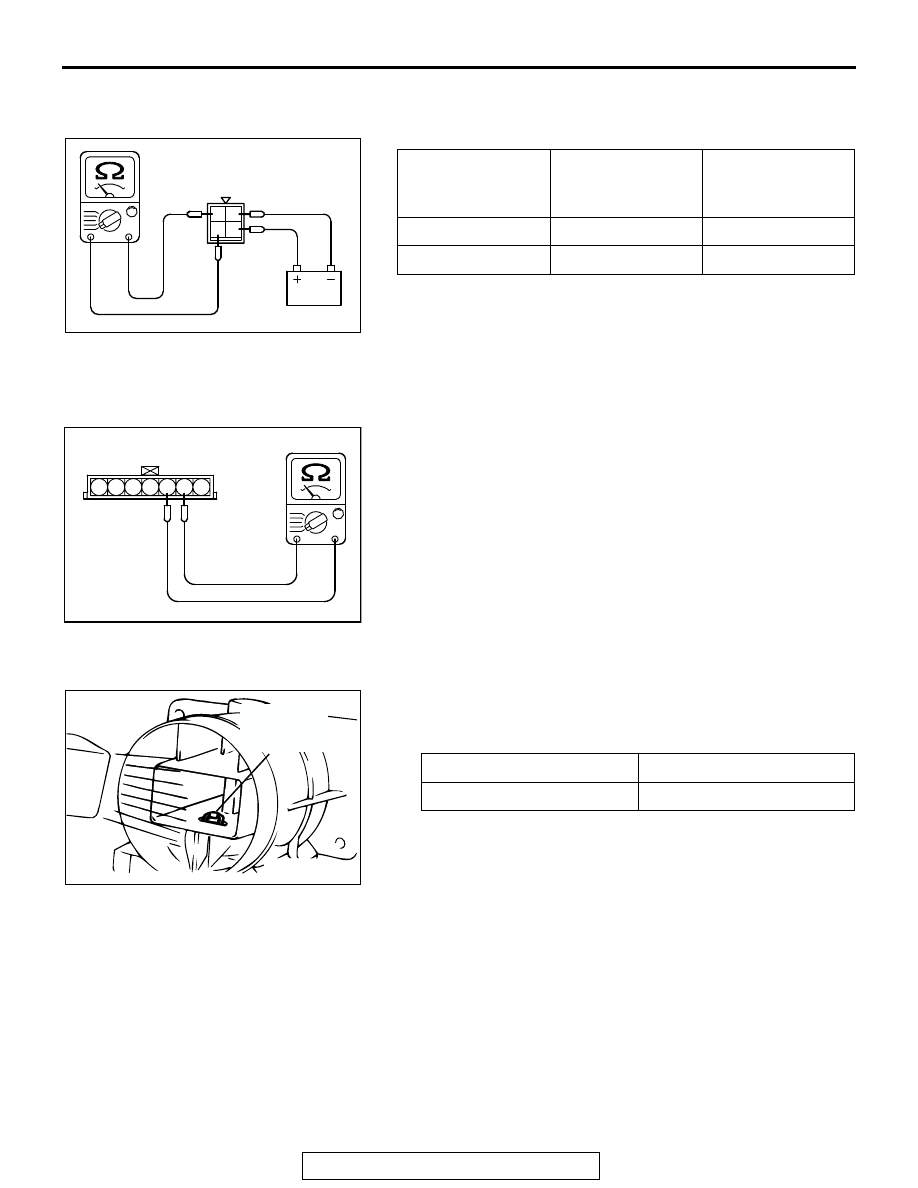
MULTIPORT FUEL INJECTION RELAY AND FUEL 
RELAY CHECK

M1131009900221

INTAKE AIR TEMPERATURE SENSOR CHECK

M1131002800524

1. Disconnect the volume airflow sensor connectors.
2. Measure resistance between terminals No. 5 and No. 6.

Standard value:

13 

 17 k [at 20°C (4°F)]

5.3 

 6.7 k [at 0°C (32°F)]

2.3 

 3.0 k [at 20°C (68°F)]

1.0 

 1.5 k [at 40°C (104°F)]

0.56 

 0.76 k [at 60°C (140°F)]

0.30 

 0.42 k [at 80°C (176°F)]

3. If not within specifications, replace the volume airflow 

sensor.

4. Measure resistance while heating the sensor using a hair 

dryer.

Normal condition:

5. If resistance does not decrease as heat increases, replace 

the volume airflow sensor assembly.

BATTERY 
VOLTAGE

BATTERY POWER 
SUPPLY 
TERMINAL

SPECIFIED 
CONDITION

Supplied

2-4

1-3

Not supplied

-

2-4

AKX01433

MFI RELAY SIDE
CONNECTOR

1 2

4

3

AB

AKX01407AB

INTAKE AIR TEMPERATURE
SENSOR SIDE CONNECTOR

1 2 3 4 5 6 7

TEMPERATURE

RESISTANCE (k

)

Higher

Smaller

AKX01621 AB

INTAKE AIR
TEMPERATURE
SENSOR

ON-VEHICLE SERVICE

TSB Revision

MULTIPORT FUEL INJECTION (MFI)

13A-890

ENGINE COOLANT TEMPERATURE SENSOR 
CHECK

M1131003100498

CAUTION

Be careful not to touch the connector (resin section) with 
the tool when removing and installing.
1. Drain engine coolant, then remove the engine coolant 

temperature sensor.

2. With the temperature sensing portion of engine coolant 

temperature sensor immersed in hot water, check the 
resistance.

Standard value:

14 

 17 k [at -20°C (-4°F)]

5.1 

 6.5 k [at 0°C (32°F)]

2.1 

 2.7 k [at 20°C (68°F)]

0.9 

 1.3 k [at 40°C (104°F)]

0.48 

 0.68 k [at 60°C (140F)]

0.26 

 0.36 k [at 80°C (176°F)]

3. If resistance deviates from the standard value greatly, 

replace the sensor.

4. Apply 3M

 AAD part number 8731 or equivalent to threaded 

portion.

5. Install the engine coolant temperature sensor and tighten it 

to the specified torque.

Tightening torque: 29 N

m (22 ft-lb)

THROTTLE POSITION SENSOR CHECK

M1131003200536

Required Special Tool:

• MB991348: Test Harness Set

.

<Checking the Terminal Resistance>
1. Disconnect the throttle position sensor connector.
2. Measure resistance between the throttle position sensor 

side connector terminal No. 1 and terminal No. 4.

Standard value: 3.5 

 6.5 k

3. Measure resistance between the throttle position sensor 

side connector terminal No. 1 and terminal No. 3.

Normal condition:

AKX01622

AKX01623 AB

Throttle valve slowly open 
until fully open from the idle 
position

Changes smoothly in 
proportion to the opening 
angle of the throttle valve

AKX01413

THROTTLE POSITION
SENSOR SIDE CONNECTOR

1 2 3 4

AB

ON-VEHICLE SERVICE

TSB Revision

MULTIPORT FUEL INJECTION (MFI)

13A-891

4. If resistance is outside the standard value, or if it doesn't 

change smoothly, replace the throttle position sensor.
NOTE: After replacement, the throttle position sensor should 
be adjusted. (Refer to 

P.13A-881

.)

.

<Check using oscilloscope>
1. Disconnect the throttle position sensor connector and 

connect the test harness special tool (MB991348) in 
between.(All terminals should be connected.)

2. Connect the oscilloscope probe to the throttle position 

sensor side connector terminal No. 3.

3. Turn the ignition switch to the "ON" position.

4. Slowly move the throttle lever from the idle position to the 

full-throttle position and check then if the waveform is free 
from any noise.

5. If any noise is recognized, replace the throttle position 

sensor.
NOTE: After replacement, the throttle position sensor should 
be adjusted. (Refer to 

P.13A-881

.)

HEATED OXYGEN SENSOR CHECK

M1131005000668

Required Special Tools:

• MB991958: Scan Tool (MUT-III Sub Assembly)

• MB991824: V.C.I

• MB991827: USB Cable

• MB991911: Main Harness B

• MB991316: Test Harness Set

• MD998464: Test Harness

.

<Left bank heated oxygen sensor (front)>
1. Using scan tool MB991958, observe HO

2

S reading. If 

values are unsatisfactory, or if a scan tool is not available, 
use the following procedure:

(1) Disconnect the heated oxygen sensor connector and 

connect special tool MB991316 to the connector on the 
heated oxygen sensor side.

(2) Make sure that there is continuity [4.5 

− 8.0 ohms at 20°C 

(68

°F)] between terminal No. 1 (red clip of special tool) 

and terminal No. 3 (blue clip of special tool) on the heated 
oxygen sensor connector

AK102987AB

1 2 3 4

THROTTLE POSITION
SENSOR CONNECTOR

OSCILLOSCOPE

MB991348

AKX01462AB

NORMAL WAVEFORM

THROTTLE LEVER
FULL-THROTTLE
POSITION

THROTTLE
LEVER
IDLE
POSITION

AKX01624 AB

MB991316

HEATED
OXYGEN
SENSOR
EQUIPMENT
SIDE
CONNECTOR

BLUE

RED

ON-VEHICLE SERVICE

TSB Revision

MULTIPORT FUEL INJECTION (MFI)

13A-892

(3) If there is no continuity, replace the heated oxygen 

sensor.

(4) Warm up the engine until engine coolant is 80

°C (176°F) 

or higher.

(5) Perform a tracing for 5 minutes or more with the engine 

speed of 4,500 r/min.

(6) Connect a digital voltage meter between terminal No. 2 

(black clip of special tool) and terminal No. 4 (white clip of 
special tool).

2. While repeatedly revving the engine, measure the heated 

oxygen sensor output voltage.

Standard value:

CAUTION

• Be very careful when connecting the jumper wire; 

incorrect connection can damage the oxygen sensor.

• Be careful the heater is broken when voltage of beyond 

8 volts is applied to the oxygen sensor heater.

NOTE: If the sufficiently high temperature (of approximate 
400

°

C or more) is not reached although the oxygen sensor 

is normal, the output voltage would be possibly low although 
the rich air-fuel ratio. Therefore, if the output voltage is low, 
use a jumper wire to connect the terminal No.1 (red clip of 
special tool) and the terminal No. 3 (blue clip of special tool) 
of the oxygen sensor with a (+) terminal and (-) terminal of 8 
volts power supply respectively, then check again.

3. If the sensor is defective, replace the heated oxygen sensor.
NOTE: For removal and installation of the heated oxygen sen-
sor, refer to GROUP 15, Exhaust Pipe and Main Muffler 

P.15-10

.

.

ENGINE

HEATED 
OXYGEN 
SENSOR 
OUTPUT 
VOLTAGE

REMARKS

When revving 
engine

0.6 

− 1.0 volt

If you make the 
air/fuel ratio rich 
by revving the 
engine repeatedly, 
a normal heated 
oxygen sensor will 
output a voltage of 
0.6 

− 1.0 volt.

AKX01624

HEATED
OXYGEN
SENSOR
COMPONENT
SIDE
CONNECTOR

MB991316

WHITE

BLACK

AN


Content   ..  367  368  369  370   ..