Mitsubishi Montero Sport (2004+). Manual - part 367


  Index      Mitsubishi     Mitsubishi Montero Sport - service repair manual 2004 year


Search            


Content   ..  365  366  367  368   ..


Mitsubishi Montero Sport (2004+). Manual - part 367


ON-VEHICLE SERVICE

TSB Revision

MULTIPORT FUEL INJECTION (MFI)

13A-881

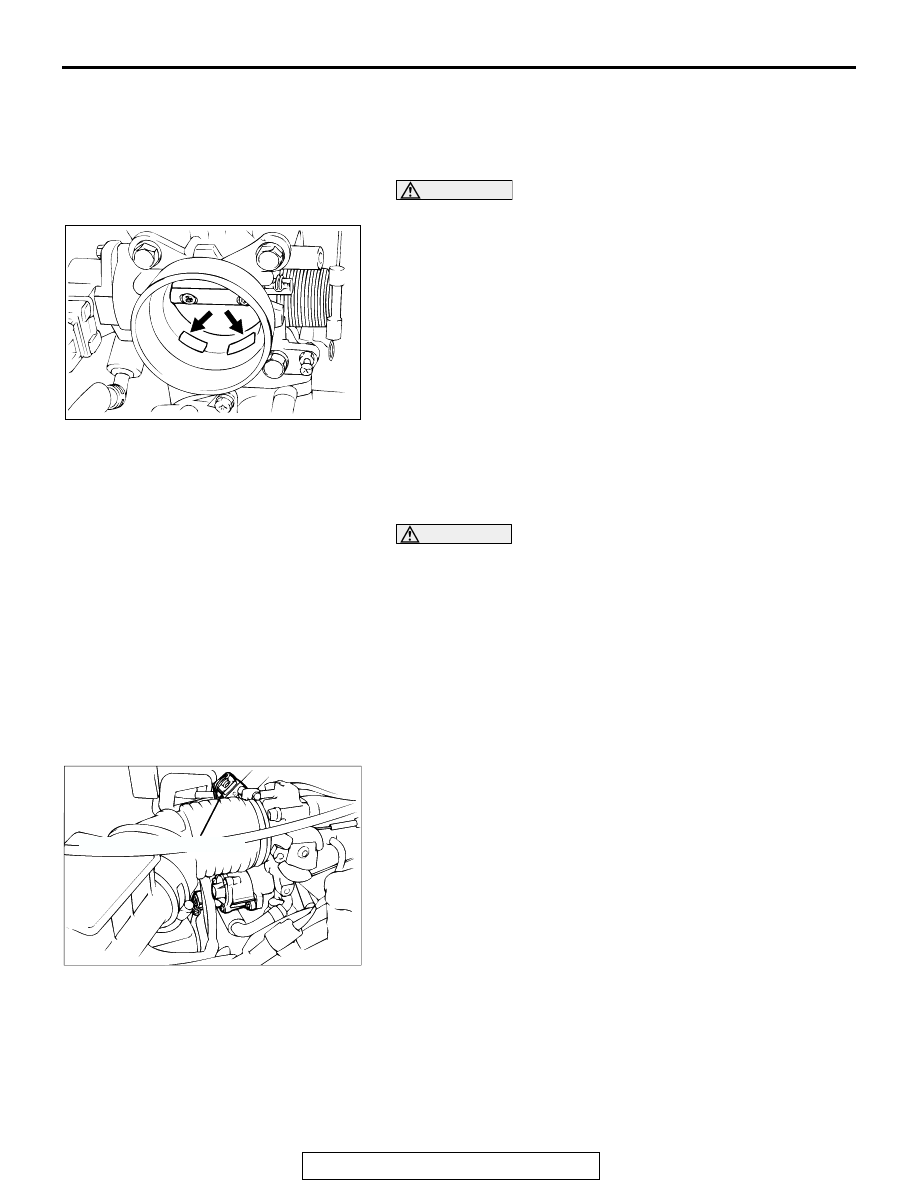
THROTTLE BODY CLEANING

M1131001000473

1. Start the engine and warm it up until the coolant is heated to 

80

°C (176°F) or higher. Stop the engine.

2. Remove the air intake hose from the throttle body.

CAUTION

Do not allow cleaning solvent to enter the bypass passage.
3. Plug the bypass passage inlet (arrow) of the throttle body.
4. Spray cleaning solvent into the valve through the throttle 

body intake port and leave it for approximately five minutes.

5. Start the engine, rev it several times and then idle it for about 

one minute. If the idling speed becomes unstable (or if the 
engine stalls) due to the bypass passage being plugged, 
slightly open the throttle valve to keep the engine running.

6. If the throttle valve deposits are not removed, repeat steps 4 

and 5.

7. Unplug the bypass passage inlet.
8. Attach the air intake hose.
9. Use scan tool MB991958 to erase any diagnostic trouble 

code.

10.Adjust the basic idle speed. (Refer to 

P.13A-883

.)

WARNING

Battery  posts, terminals and related accessories con-
tain lead and lead compounds. WASH HANDS AFTER 
HANDLING.

NOTE: If the engine hunts while idling after adjustment of 
the basic idle speed, disconnect the negative cable from the 
battery for 10 seconds or more, and then reconnect it and 
run the engine at idle for about 10 minutes after the engine 
is warmed up.

THROTTLE POSITION SENSOR ADJUSTMENT

M1131001100555

Required Special Tools:

• MB991958: Scan Tool (MUT-III Sub Assembly)

• MB991824: V.C.I

• MB991827: USB Cable

• MB991911: Main Harness B

• MB991348: Test Harness Set

AK303656AB

AK000332AC

THROTTLE POSITION SENSOR

ON-VEHICLE SERVICE

TSB Revision

MULTIPORT FUEL INJECTION (MFI)

13A-882

CAUTION

To prevent damage to scan tool MB991958, always turn the 
ignition switch to the "LOCK" (OFF) position before con-
necting or disconnecting scan tool MB991958.
1. Connect scan tool MB991958 to the data link connector. 

When not using the scan tool MB991958, proceed as 
follows.

(1) )Disconnect the throttle position sensor connector, and 

connect the special tool MB991348 in between. (All 
terminals should be connected.)

(2) Connect a digital voltmeter between throttle position 

sensor terminals No. 3 (sensor output) and No. 1 (sensor 
ground).

2. Turn the ignition switch to the "ON" position. (Do not start 

the engine.)

3. Check the throttle position sensor output voltage.

Standard value: 535 

 735 mililvolts

4. If not within the standard value range, adjust by loosening 

throttle position sensor mounting bolts and turning the 
throttle position sensor body. After adjusting, tighten the 
bolts securely.

5. Turn the ignition switch to the "LOCK" (OFF) position.
6. Disconnect scan tool MB991958. 

When the scan tool MB991958 is not used, remove special 
tool MB991348, and connect the throttle position sensor 
connector.
NOTE: If a diagnostic trouble code is sent while adjusting 
the throttle position sensor, use scan tool MB991958 to 
erase the diagnostic trouble code.

AK303629AB

MB991911

MB991827

MB991824 

16-PIN

AKX01636AB

TERMINAL 3
(SENSOR OUTPUT)

TERMINAL 1
(SENSOR 
 GROUND)

MB991348

ON-VEHICLE SERVICE

TSB Revision

MULTIPORT FUEL INJECTION (MFI)

13A-883

BASIC IDLE SPEED ADJUSTMENT

M1131001800617

Required Special Tools:

• MB991958: Scan Tool (MUT-III Sub Assembly)

• MB991824: V.C.I

• MB991827: USB Cable

• MB991911: Main Harness B

NOTE: The standard idling speed has been adjusted with the 
speed adjusting screw (SAS), by the manufacturer. There 
should be no need for readjustment.
NOTE: If the adjustment has been changed by mistake, the idle 
speed may become too high or the idle speed may drop too low 
when loads A/C, defogger, etc. are placed on the engine. If this 
occurs, adjust by the following procedure.
NOTE: The adjustment, if made, should be made after first con-
firming that the spark plugs, the injectors, the idle air control 
motor, compression, etc., are all normal.
1. The vehicle should be prepared as follows before the 

inspection and adjustment.

• Engine coolant temperature: 80 − 95° C (176 − 203°F)

• Lights and all accessories: OFF

• Transmission: P range

CAUTION

To prevent damage to scan tool MB991958, always turn the 
ignition switch to the "LOCK" (OFF) position before con-
necting or disconnecting scan tool MB991958.
2. Connect scan tool MB991958 to the data link connector 

(16-pin).
NOTE: When scan tool MB991958 is connected, the diag-
nostic test mode control terminal should be grounded.

3. Start the engine and run at idle.
4. Select the item number 30 of the scan tool Actuator test.

NOTE: Use the scan tool to hold the IAC motor at the basic 
step to adjust the basic idle speed.

5. Check the idle speed.

Standard value: 700 

± 50 r/min

NOTE: The engine speed may be 20 to 100 r/min lower than 
indicated above for a new vehicle [driven approximately 500 
km (300 mile) or less], but no adjustment is necessary.
NOTE: If the engine stalls or the engine speed is low even 
though the vehicle has been driven approximately 500 km 
(300 mile) or more, it is probable that the throttle valve is 
dirty, so clean it. (Refer to 

P.13A-881

.)

AK303629AB

MB991911

MB991827

MB991824 

16-PIN

ON-VEHICLE SERVICE

TSB Revision

MULTIPORT FUEL INJECTION (MFI)

13A-884

6. If not within the standard value range, turn the speed 

adjusting screw (SAS) to make the necessary adjustment.

7. Press the scan tool clear key, and release the IAC motor 

Actuator test mode.
NOTE: Unless the A/C motor is released, the Actuator test 
mode will continue 27 minutes.

8. Turn the ignition switch to the "LOCK" (OFF) position.
9. Disconnect scan tool MB991958.
10.Start the engine again and let it idle for about 10 minutes. 

Check that the idling condition is normal.

FUEL PRESSURE TEST

M1131001900551

Required Special Tools:

• MB991958: Scan Tool (MUT-III Sub Assembly)

• MB991824: V.C.I

• MB991827: USB Cable

• MB991911: Main Harness B

• MB991637: Fuel Pressure Gauge Set

• MD998709: Adaptor Hose

• MD998742: Hose Adaptor

1. Release residual pressure from the fuel line to prevent fuel 

spray. (Refer to 

P.13A-887

.)

WARNING

To prevent a fire, cover the hose connection with 
shop towels to prevent splashing of fuel that could be 
caused by some residual pressure in the fuel pipe 
line.

2. Disconnect the fuel high-pressure hose at the fuel rail side.
3. Assemble the fuel pressure measurement tools as follows.

<When using the fuel pressure gauge>

1. Remove the union joint and bolt from special tool 

MD998709 (adapter hose) and instead attach special tool 
MD998742 (hose adapter) to the adapter hose.

2. Place a suitable O-ring or gasket on the assembled special 

tools MD998709 and MD998742 and install the fuel pres-
sure gauge.

3. Install the assembled fuel pressure measurement tools 

between the fuel rail and fuel high-pressure hose.

AKX01455

AKX01456

FUEL-
RAIL

AC

FUEL
HIGH-PRESSURE
HOSE

AKX01457AH

FUEL PRESSURE 
GAUGE

O-RING OR GASKET

MD998709

MD998742

FUEL 
RAIL 

FUEL
HIGH-PRESSURE
HOSE


Content   ..  365  366  367  368   ..