Mitsubishi Montero Sport (2004+). Manual - part 355


  Index      Mitsubishi     Mitsubishi Montero Sport - service repair manual 2004 year


Search            


Content   ..  353  354  355  356   ..


Mitsubishi Montero Sport (2004+). Manual - part 355


MULTIPORT FUEL INJECTION (MFI) DIAGNOSIS

TSB Revision

MULTIPORT FUEL INJECTION (MFI)

13A-833

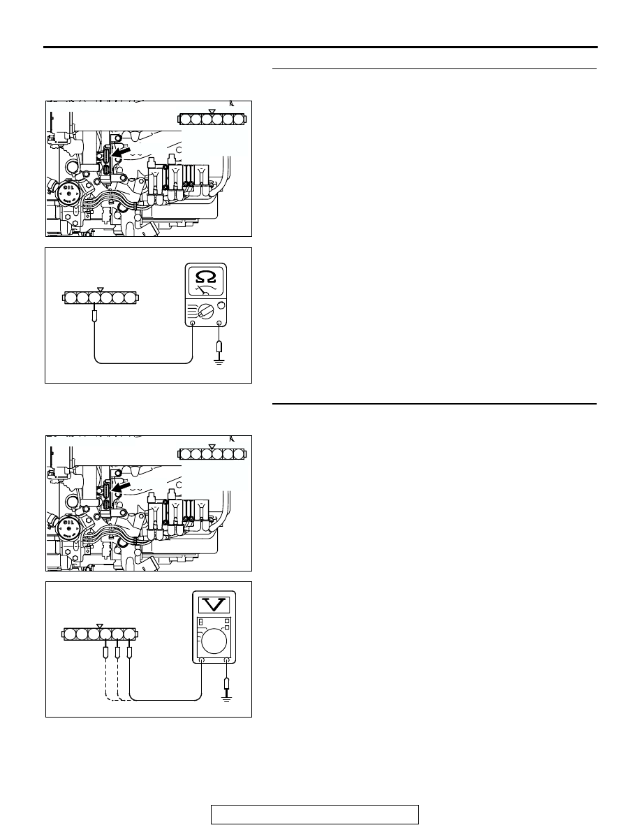
STEP 8. Check for continuity at ignition power transistor 
harness side connector A-05.
(1) Disconnect the connector A-05 and measure at the harness 

side.

(2) Check for the continuity between terminal No. 4 and 

ground.

• Should be less than 2 ohms.

Q: Does continuity exist?

YES : Go to Step 9.
NO :  Repair harness wire between ignition power transistor 

connector A-05 (terminal No. 4) and ground. Then 
confirm that the malfunction symptom is eliminated.

STEP 9. Measure the circuit at ignition power transistor 
connector A-05.
(1) Disconnect the connector A-05 and measure at the harness 

side.

(2) Crank the engine.

(3) Measure the voltage between terminals No. 1, No. 2, No. 3 

and ground.

• Voltage should be between 0.5 and 4.0 volts.

(4) Turn the ignition switch to the "LOCK" (OFF) position.
Q: Is battery positive voltage (approximately 12 volts) 

present?
YES : 
Go to Step 12.
NO :  Go to Step 10.

AK200475

3

4

5

6

1

2

CONNECTOR: A-05

AB

HARNESS 
CONNECTOR:
COMPONENT 
SIDE

A-05(B)

AKX01445

A-05 HARNESS 
CONNECTOR: 
COMPONENT SIDE

1

2

3

4

5

6

AE

AK200475

3

4

5

6

1

2

CONNECTOR: A-05

AB

HARNESS 
CONNECTOR:
COMPONENT 
SIDE

A-05(B)

AKX01446

A-05 HARNESS 
CONNECTOR: 
COMPONENT SIDE

4

5

6

3 2 1

AE

MULTIPORT FUEL INJECTION (MFI) DIAGNOSIS

TSB Revision

MULTIPORT FUEL INJECTION (MFI)

13A-834

STEP 10. Check harness connector C-89 at PCM for 
damage.
Q: Is the harness connector in good condition?

YES : Go to Step 11.
NO :  Repair or replace it. Refer to GROUP 00E, Harness 

Connector Inspection 

P.00E-2

. Then confirm that the 

malfunction symptom is eliminated.

STEP 11. Check for open circuit between ignition power 
transistor connector A-05 (terminals No. 1, No. 2, No. 3) 
and PCM connector C-89 (terminals No. 11, No. 12, No. 13).
Q: Is the harness wire in good condition?

YES : Replace the PCM. Then confirm that the malfunction 

symptom is eliminated.

NO :  Repair it. Then confirm that the malfunction symptom 

is eliminated.

AK103914

2

3

4

5

6

7

8

9

11

12

13

14

15

16

17

18

19

20

30

21

22

23

24

25

26

27

28

29

31

32

33

34

35

1

10

AB

CONNECTOR: C-89

C-89(GR)

HARNESS CONNECTOR:
COMPONENT SIDE

AK200475

3

4

5

6

1

2

CONNECTOR: A-05

AB

HARNESS 
CONNECTOR:
COMPONENT 
SIDE

A-05(B)

AK103914

2

3

4

5

6

7

8

9

11

12

13

14

15

16

17

18

19

20

30

21

22

23

24

25

26

27

28

29

31

32

33

34

35

1

10

AB

CONNECTOR: C-89

C-89(GR)

HARNESS CONNECTOR:
COMPONENT SIDE

MULTIPORT FUEL INJECTION (MFI) DIAGNOSIS

TSB Revision

MULTIPORT FUEL INJECTION (MFI)

13A-835

STEP 12. Measure the circuit at ignition power transistor 
connector A-05.
(1) Disconnect the connector A-05 and measure at the harness 

side.

(2) Turn the ignition switch to the "ON" position.

(3) Measure the voltage between terminal  No. 5 and ground.

• Voltage should be 4 volts or more.

(4) Turn the ignition switch to the "LOCK" (OFF) position.
Q: Is the measured voltage 4 volts or more?

YES : Replace the ignition power transistor. Then confirm 

that the malfunction symptom is eliminated.

NO :  Go to Step 13.

STEP 13. Check harness connector C90 at PCM for 
damage.
Q: Is the harness connector in good condition?

YES : Go to Step 14.
NO :  Repair or replace it. Refer to GROUP 00E, Harness 

Connector Inspection 

P.00E-2

. Then confirm that the 

malfunction symptom is eliminated.

AK200475

3

4

5

6

1

2

CONNECTOR: A-05

AB

HARNESS 
CONNECTOR:
COMPONENT 
SIDE

A-05(B)

AKX01447

A-05 HARNESS 
CONNECTOR: 
COMPONENT SIDE

6 5 4 3 2 1

AE

AK103762

42

43

48

49

50

51

52

53

54

55

56

57

46 45 44

58

59

60

61

62

63

64

65

66

47

41

AB

CONNECTOR: C-90

C-90(GR)

HARNESS CONNECTOR:
COMPONENT SIDE

MULTIPORT FUEL INJECTION (MFI) DIAGNOSIS

TSB Revision

MULTIPORT FUEL INJECTION (MFI)

13A-836

STEP 14. Check for open circuit between ignition power 
transistor connector A-05 (terminal No. 5) and PCM 
connector C-90 (terminal No. 43).

NOTE: Check harness after checking intermediate connector 
C-71. If intermediate connector is damaged, repair or replace 
them. Refer to GROUP 00E, Harness Connector Inspection 

P.00E-2

. Then confirm that the malfunction symptom is elimi-

nated.
Q: Is the harness wire in good condition?

YES : Replace the PCM. Then confirm that the malfunction 

symptom is eliminated.

NO :  Repair it. Then confirm that the malfunction symptom 

is eliminated.

AK200475

3

4

5

6

1

2

CONNECTOR: A-05

AB

HARNESS 
CONNECTOR:
COMPONENT 
SIDE

A-05(B)

AK103762

42

43

48

49

50

51

52

53

54

55

56

57

46 45 44

58

59

60

61

62

63

64

65

66

47

41

AB

CONNECTOR: C-90

C-90(GR)

HARNESS CONNECTOR:
COMPONENT SIDE


Content   ..  353  354  355  356   ..