Mitsubishi Montero Sport (2004+). Manual - part 353


  Index      Mitsubishi     Mitsubishi Montero Sport - service repair manual 2004 year


Search            


Content   ..  351  352  353  354   ..


Mitsubishi Montero Sport (2004+). Manual - part 353


MULTIPORT FUEL INJECTION (MFI) DIAGNOSIS

TSB Revision

MULTIPORT FUEL INJECTION (MFI)

13A-825

STEP 6. Check connector B-01 at transmission range 
switch for damage.
Q: Is the connector in good condition?

YES : Go to Step 7.
NO :  Repair or replace it. Refer to GROUP 00E, Harness 

Connector Inspection 

P.00E-2

. Then confirm that the 

malfunction symptom is eliminated.

STEP 7. Check the transmission range switch.
Refer to GROUP 23A, On-vehicle Service 

− Essential Service − 

Transmission range switch continuity check 

P.23A-435

.

Q: Are there any abnormalities?

YES : Go to Step 8.
NO :  Repair or replace it. Then confirm that the malfunction 

symptom is eliminated.

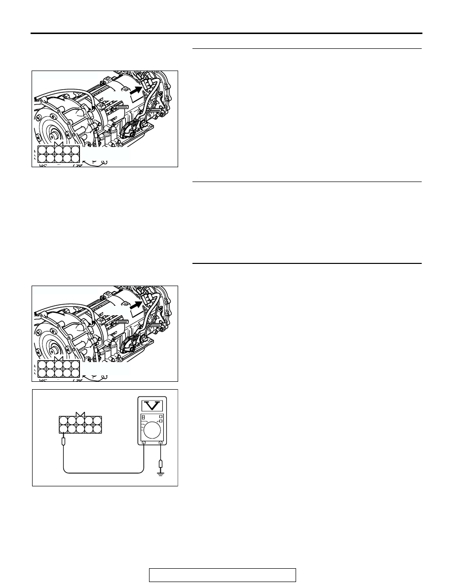
STEP 8. Measure the power supply voltage at transmission 
range switch connector B-01.
(1) Disconnect the connector B-01 and measure at the harness 

side.

(2) Turn the ignition switch to the "START" position.

(3) Measure the voltage between terminal No. 10 and ground.

• Voltage should be battery positive voltage.

(4) Turn the ignition switch to the "LOCK" (OFF) position.
Q: Is battery positive voltage (approximately 12 volts) 

present?
YES : 
Go to Step 9.
NO :  Check connector C-30 and C-41 at intermediate 

connector for damage, and repair or replace as 
required. Refer to GROUP 00E, Harness Connector 
Inspection 

P.00E-2

If intermediate connector are in 

good condition, repair harness wire between ignition 
switch connector D-15 (terminal No. 5) and 
transmission range position switch connector B-01 
(terminal No. 10) because of open circuit. Then 
confirm that the malfunction symptom is eliminated.

AK200050

5

10

4 3 2 1

6

7

8

9

AB

CONNECTOR: B-01

B-01(B)

HARNESS CONNECTOR:
COMPONENT SIDE

AK200050

5

10

4 3 2 1

6

7

8

9

AB

CONNECTOR: B-01

B-01(B)

HARNESS CONNECTOR:
COMPONENT SIDE

AK000651

5

10

4 3 2 1

6

7

8

9

B-01 HARNESS 
CONNECTOR: 
COMPONENT SIDE

AD

MULTIPORT FUEL INJECTION (MFI) DIAGNOSIS

TSB Revision

MULTIPORT FUEL INJECTION (MFI)

13A-826

STEP 9. Check for open circuit and short circuit to ground 
and harness damage between transmission range switch 
connector B-01 (terminal No. 9) and starter relay connector 
A-50X (terminal No. 3).

NOTE: Check harness after checking intermediate connector 
C-30 and C-41. If intermediate connector are damaged, repair 
or replace them. Refer to GROUP 00E, Harness Connector 
Inspection 

P.00E-2

. Then confirm that the malfunction symp-

tom is eliminated.
Q: Is the harness wire in good condition?

YES : Go to Step 10.
NO :  Repair it. Then confirm that the malfunction symptom 

is eliminated.

STEP 10. Check connector C-90 at PCM for damage.
Q: Is the connector in good condition?

YES : Go to Step 11.
NO :  Repair or replace it. Refer to GROUP 00E, Harness 

Connector Inspection 

P.00E-2

. Then confirm that the 

malfunction symptom is eliminated.

AK200050

5

10

4 3 2 1

6

7

8

9

AB

CONNECTOR: B-01

B-01(B)

HARNESS CONNECTOR:
COMPONENT SIDE

AK303397

1

4

3

2

AB

CONNECTOR: A-50X

A-50X

HARNESS CONNECTOR:
COMPONENT SIDE

AK103762

42

43

48

49

50

51

52

53

54

55

56

57

46 45 44

58

59

60

61

62

63

64

65

66

47

41

AB

CONNECTOR: C-90

C-90(GR)

HARNESS CONNECTOR:
COMPONENT SIDE

MULTIPORT FUEL INJECTION (MFI) DIAGNOSIS

TSB Revision

MULTIPORT FUEL INJECTION (MFI)

13A-827

STEP 11. Check for open circuit and short circuit to ground 
and harness damage between starter relay connector 
A-50X (terminal No. 2) and PCM connector C-90 (terminal 
No. 58).
Q: Is the harness wire in good condition?

YES : Replace the PCM. Then confirm that the malfunction 

symptom is eliminated.

NO :  Repair it. Then confirm that the malfunction symptom 

is eliminated.

AK303397

1

4

3

2

AB

CONNECTOR: A-50X

A-50X

HARNESS CONNECTOR:
COMPONENT SIDE

AK103762

42

43

48

49

50

51

52

53

54

55

56

57

46 45 44

58

59

60

61

62

63

64

65

66

47

41

AB

CONNECTOR: C-90

C-90(GR)

HARNESS CONNECTOR:
COMPONENT SIDE

MULTIPORT FUEL INJECTION (MFI) DIAGNOSIS

TSB Revision

MULTIPORT FUEL INJECTION (MFI)

13A-828

INSPECTION PROCEDURE 31: Ignition Circuit System.

BL

ACK

BL

ACK

-

WHITE

BL

ACK

-

WHITE

BL

ACK

-

WHITE

BL

ACK

-W

HITE

BL

UE

BL

ACK

-YELL

OW

WHITE

WHITE

WHITE

BL

ACK

-

WHITE

BL

ACK

-

WHITE

BROWN

BROWN-

WHITE

BROWN-

RED

AK303655

Ignition Circuit

IG1

ST

LOCK

ACC

IG2

2

IGNITION
SWITCH

R

12

3 4 5 6

1 2

A-05
(MU802725)

13

11 12

A-06
(MU802723)

2

1

A-45

A-06

A-05

1 2

A-44

1 2

A-46

1

1

1

2

13

12

11

6

43

11

13

2

2

IGNITION
COIL

2

5

3

1

IGNITION POWER
TRANSISTOR

POWERTRAIN
CONTROL
MODULE (PCM)

C-89

SPARK
PLUG

No.6

No.3

No.5

No.2

No.4

No.1

4

3

JUNCTION
BLOCK

4

TO TACHOMETER

24

23

25

ENGINE SPEED
DETECTION
CONNECTOR

1

A-37

JOINT
CONNECTOR (4)

1

26

1 2 3
4 5 6

D-15

1
3

2
4

D-08
(MU801342)

1

10

2 3 4 5 6 7 8 9

11

12 13 14 15 16 17 18 19 20 21 22

23 24 25 26 27 28 29 30 31 32 33

C-71

47

41

42 43

48 49 50 51 52 53 54 55 56 57

46

45

44

58

59

60 61 62 63

64 65 66

C-90
(MU803781)

10

2

3 4

5 6

7 8

9

11 12 13 14 15 16 17 18 19 20

30

21 22 23

24

25

26 27 28 29

31 32 33

34 35

1

C-89
(MU803784)

WHITE

WHITE


Content   ..  351  352  353  354   ..