Mitsubishi Montero Sport (2004+). Manual - part 325


  Index      Mitsubishi     Mitsubishi Montero Sport - service repair manual 2004 year


Search            


Content   ..  323  324  325  326   ..


Mitsubishi Montero Sport (2004+). Manual - part 325


MULTIPORT FUEL INJECTION (MFI) DIAGNOSIS

TSB Revision

MULTIPORT FUEL INJECTION (MFI)

13A-713

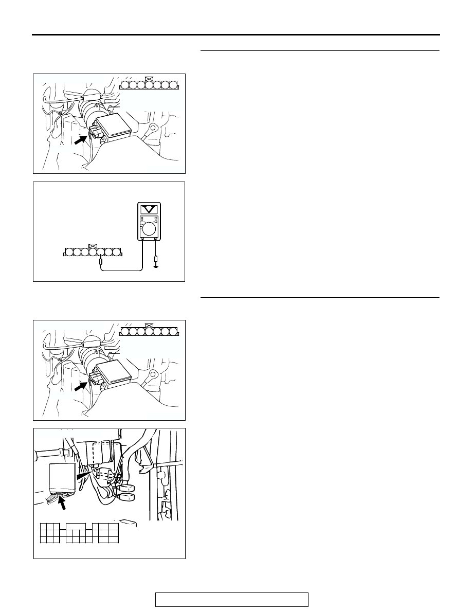
STEP 7. Measure the ground voltage at barometric 
pressure sensor connector A-01 by backprobing.
(1) Do not disconnect the connector A-01.
(2) Turn the ignition switch to the "ON" position.

(3) Measure the voltage between terminal No. 5 and ground by 

backprobing.

• Voltage should be 0.5 volt or less.

(4) Turn the ignition switch to the "LOCK" (OFF) position.
Q: Is the measured voltage 0.5 volt or less?

YES : Go to Step 10.
NO :  Go to Step 8.

STEP 8. Check connector A-01 at the barometric pressure 
sensor and connector C-90 at PCM for damage.
Q: Is the connector in good condition?

YES : Go to Step 9.
NO :  Repair or replace it. Refer to GROUP 00E, Harness 

Connector Inspection 

P.00E-2

. Then go to Step 12.

AK103913

3

4

5

1

2

6

7

CONNECTOR: A-01

A-01(B)

AB

HARNESS 
CONNECTOR: 
COMPONENT SIDE

AKX01517

A-01 HARNESS 
CONNECTOR: 
HARNESS SIDE

1 2 3 4 5 6 7

AI

AK103913

3

4

5

1

2

6

7

CONNECTOR: A-01

A-01(B)

AB

HARNESS 
CONNECTOR: 
COMPONENT SIDE

AK103762

42

43

48

49

50

51

52

53

54

55

56

57

46 45 44

58

59

60

61

62

63

64

65

66

47

41

AB

CONNECTOR: C-90

C-90(GR)

HARNESS CONNECTOR:
COMPONENT SIDE

MULTIPORT FUEL INJECTION (MFI) DIAGNOSIS

TSB Revision

MULTIPORT FUEL INJECTION (MFI)

13A-714

STEP 9. Check for open circuit between barometric 
pressure sensor connector A-01 (terminal No. 5) and PCM 
connector C-90 (terminal No. 57).

NOTE: Check harness after checking intermediate connector 
C-71. If intermediate connector is damaged, repair or replace it. 
Refer to GROUP 00E, Harness Connector Inspection 

P.00E-2

Then go to Step 12.
Q: Is the harness wire in good condition?

YES : Replace the PCM. Then go to Step 12.
NO :  Repair it. Then go to Step 12.

STEP 10. Check connector A-01 at barometric pressure 
sensor for damage.
Q: Is the connector in good condition?

YES : Go to Step 11.
NO :  Repair or replace it. Refer to GROUP 00E, Harness 

Connector Inspection 

P.00E-2

. Then go to Step 12.

AK103913

3

4

5

1

2

6

7

CONNECTOR: A-01

A-01(B)

AB

HARNESS 
CONNECTOR: 
COMPONENT SIDE

AK103762

42

43

48

49

50

51

52

53

54

55

56

57

46 45 44

58

59

60

61

62

63

64

65

66

47

41

AB

CONNECTOR: C-90

C-90(GR)

HARNESS CONNECTOR:
COMPONENT SIDE

AK103913

3

4

5

1

2

6

7

CONNECTOR: A-01

A-01(B)

AB

HARNESS 
CONNECTOR: 
COMPONENT SIDE

MULTIPORT FUEL INJECTION (MFI) DIAGNOSIS

TSB Revision

MULTIPORT FUEL INJECTION (MFI)

13A-715

STEP 11. Check connector C-90 at PCM for damage.
Q: Is the connector in good condition?

YES : Replace the volume airflow sensor. Then go to Step 

12.

NO :  Repair or replace it. Refer to GROUP 00E, Harness 

Connector Inspection 

P.00E-2

. Then go to Step 12.

STEP 12. Test the OBD-II drive cycle.
(1) Carry out a test drive with the drive cycle pattern. Refer to 

Diagnostic Function 

− OBD-II Drive Cycle − Procedure 6 − 

Other Monitor 

P.13A-4

.

(2) Check the diagnostic trouble code (DTC).
Q: Is DTC P2229 set?

YES : Repeat the troubleshooting.
NO :  The procedure is complete.

AK103762

42

43

48

49

50

51

52

53

54

55

56

57

46 45 44

58

59

60

61

62

63

64

65

66

47

41

AB

CONNECTOR: C-90

C-90(GR)

HARNESS CONNECTOR:
COMPONENT SIDE

Continue

MULTIPORT FUEL INJECTION (MFI) DIAGNOSIS

TSB Revision

MULTIPORT FUEL INJECTION (MFI)

13A-716

13A

SYMPTOM PROCEDURES

INSPECTION PROCEDURE 1: Communication with Scan Tool Is Not Possible. (Comunication with All 
Systems Is Not Possible.)

1

1

1

1

1

2 3

4 5

6 7 8

2 3 4 5 6 7 8

9

2 3

4 5 6 7

8 9 10

10

10 11 12

11 12 13 14 15 16

11 12 13 14 15 16

9

BL

ACK

BL

ACK

WHITE-

RED

RED

AK303391

Data Link Connector Circuit

BL

ACK

RED

-

BL

ACK

RED

-

BL

ACK

2

A-54X
MU801541

FUSIBLE LINK (8)

6

2

5

RELAY
BOX

C-69

JUNCTION
BLOCK

4

16

5

D-01

D-06

DATA LINK
CONNECTOR

D-06

D-01

AK200037AB

A-54X

CONNECTOR: A-54X

AK200038AB

CONNECTOR: C-69

DATA LINK
CONNECTOR

C-69(B)


Content   ..  323  324  325  326   ..