Mitsubishi Montero Sport (2004+). Manual - part 323


  Index      Mitsubishi     Mitsubishi Montero Sport - service repair manual 2004 year


Search            


Content   ..  321  322  323  324   ..


Mitsubishi Montero Sport (2004+). Manual - part 323


MULTIPORT FUEL INJECTION (MFI) DIAGNOSIS

TSB Revision

MULTIPORT FUEL INJECTION (MFI)

13A-705

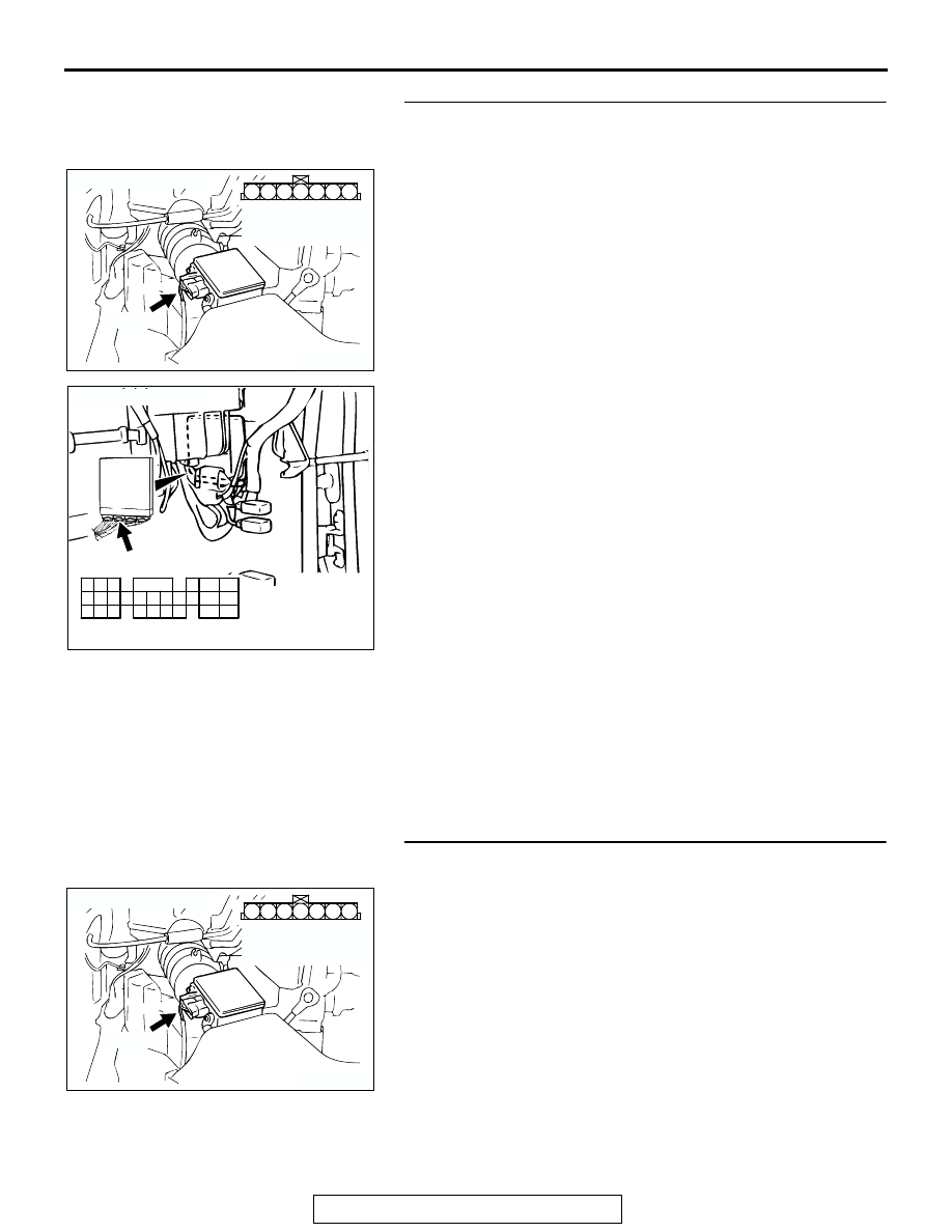
STEP 14. Check for harness damage between barometric 
pressure sensor connector A-01 (terminal No. 5) and PCM 
connector C-90 (terminal No. 57).

NOTE: Check harness after checking intermediate connector 
C-71. If intermediate connector is damaged, repair or replace it. 
Refer to GROUP 00E, Harness Connector Inspection 

P.00E-2

Then go to Step 18.
Q: Is the harness wire in good condition?

YES : Replace the PCM. Then go to Step 18.
NO :  Repair it. Then go to Step 18.

STEP 15. Check connector A-01 at barometric pressure 
sensor for damage.
Q: Is the connector in good condition?

YES : Go to Step 16.
NO :  Repair or replace it. Refer to GROUP 00E, Harness 

Connector Inspection 

P.00E-2

. Then go to Step 18.

AK103913

3

4

5

1

2

6

7

CONNECTOR: A-01

A-01(B)

AB

HARNESS 
CONNECTOR: 
COMPONENT SIDE

AK103762

42

43

48

49

50

51

52

53

54

55

56

57

46 45 44

58

59

60

61

62

63

64

65

66

47

41

AB

CONNECTOR: C-90

C-90(GR)

HARNESS CONNECTOR:
COMPONENT SIDE

AK103913

3

4

5

1

2

6

7

CONNECTOR: A-01

A-01(B)

AB

HARNESS 
CONNECTOR: 
COMPONENT SIDE

MULTIPORT FUEL INJECTION (MFI) DIAGNOSIS

TSB Revision

MULTIPORT FUEL INJECTION (MFI)

13A-706

STEP 16. Check connector C-90 at PCM for damage.
Q: Is the connector in good condition?

YES : Go to Step 17.
NO :  Repair or replace it. Refer to GROUP 00E, Harness 

Connector Inspection 

P.00E-2

. Then go to Step 18.

STEP 17. Check for short circuit to ground and harness 
damage between barometric pressure sensor connector 
A-01 (terminal No. 2) and PCM connector C-90 (terminal 
No. 55).
Q: Is the harness wire in good condition?

YES : Replace the volume airflow sensor. Then go to Step 

18.

NO :  Repair it. Then go to Step 18.

AK103762

42

43

48

49

50

51

52

53

54

55

56

57

46 45 44

58

59

60

61

62

63

64

65

66

47

41

AB

CONNECTOR: C-90

C-90(GR)

HARNESS CONNECTOR:
COMPONENT SIDE

AK103913

3

4

5

1

2

6

7

CONNECTOR: A-01

A-01(B)

AB

HARNESS 
CONNECTOR: 
COMPONENT SIDE

AK103762

42

43

48

49

50

51

52

53

54

55

56

57

46 45 44

58

59

60

61

62

63

64

65

66

47

41

AB

CONNECTOR: C-90

C-90(GR)

HARNESS CONNECTOR:
COMPONENT SIDE

MULTIPORT FUEL INJECTION (MFI) DIAGNOSIS

TSB Revision

MULTIPORT FUEL INJECTION (MFI)

13A-707

STEP 18. Test the OBD-II drive cycle.
(1) Carry out a test drive with the drive cycle pattern. Refer to 

Diagnostic Function 

− OBD-II Drive Cycle − Procedure 6 − 

Other Monitor 

P.13A-4

.

(2) Check the diagnostic trouble code (DTC).
Q: Is DTC P2228 set?

YES : Repeat the troubleshooting.
NO :  The procedure is complete.

DTC P2229: Barometric Pressure Circuit High Input

GREEN-

YELL

OW

AK302268

Barometric Pressure Sensor Circuit

PINK

BL

ACK

BL

ACK

5V

POWERTRAIN CONTROL MODULE (PCM)

46

1

55

57

15

2

5

12

BAROMETRIC PRESSURE SENSOR
(INCORPORATED IN VOLUME
AIRFLOW SENSOR)

1 2 3 4 5 6 7

A-01

1

10

2 3 4 5 6 7 8 9

11

12 13 14 15 16 17 18 19 20 21 22

23 24 25 26 27 28 29 30 31 32 33

C-71

JOINT
CONNEC-
TOR (4)

47

41

42 43

48 49 50 51 52 53 54 55 56 57

46

45

44

58

59

60 61 62 63

64 65 66

C-90
(MU803781)

MULTIPORT FUEL INJECTION (MFI) DIAGNOSIS

TSB Revision

MULTIPORT FUEL INJECTION (MFI)

13A-708

.

CIRCUIT OPERATION

• A 5-volt voltage is supplied to the barometric 

pressure sensor power terminal (terminal No. 1) 
from the PCM (terminal No. 46). The ground ter-
minal (terminal No. 5) is grounded with PCM (ter-
minal No. 57).

• A voltage that is proportional to the atmospheric 

pressure is sent to the PCM (terminal No. 55) 
from the barometric pressure sensor output ter-
minal (terminal No. 2).

.

TECHNICAL DESCRIPTION

• The barometric pressure sensor outputs a volt-

age which corresponds to the barometric pres-
sure.

• The PCM checks whether this voltage is within a 

specified range.

.

DESCRIPTIONS OF MONITOR METHODS
Barometric pressure sensor output voltage is out of 

reasonable barometric pressure range.

.

MONITOR EXECUTION
Continuous

.

MONITOR EXECUTION CONDITIONS (Other 
monitor and Sensor)

Other Monitor (There is no temporary DTC stored 

in memory for the item monitored below)

• Not applicable

Sensor (The sensor below is determined to be 

normal)

• Not applicable

.

AK103908

CONNECTOR: A-01

BAROMETRIC
PRESSURE
SENSOR

A-01(B)

AC

AK103912AB

CONNECTOR: C-71

C-71

AK103738AC

CONNECTOR: C-90

PCM

C-90(GR)


Content   ..  321  322  323  324   ..