Mitsubishi Montero Sport (2004+). Manual - part 321


  Index      Mitsubishi     Mitsubishi Montero Sport - service repair manual 2004 year


Search            


Content   ..  319  320  321  322   ..


Mitsubishi Montero Sport (2004+). Manual - part 321


MULTIPORT FUEL INJECTION (MFI) DIAGNOSIS

TSB Revision

MULTIPORT FUEL INJECTION (MFI)

13A-697

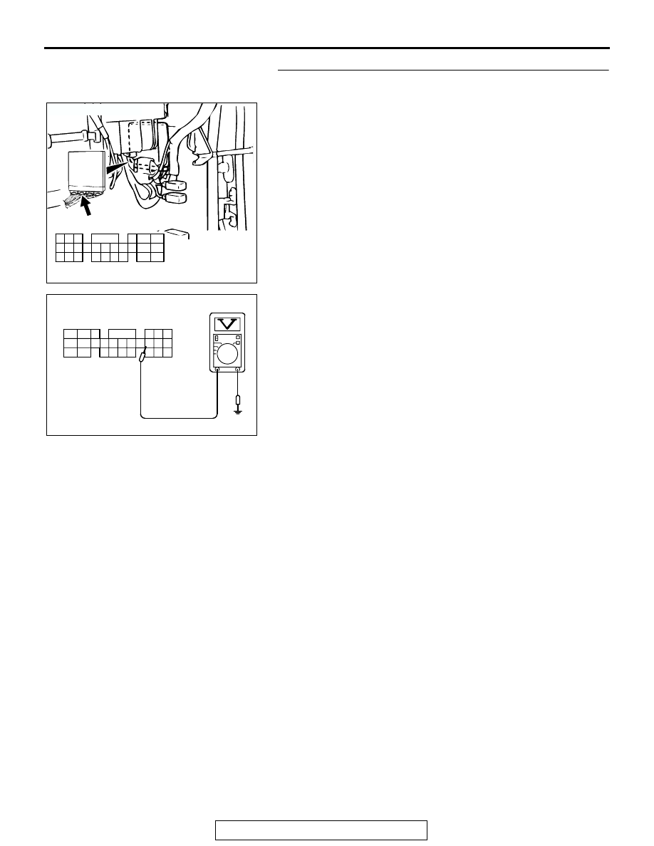
STEP 3. Measure the sensor output voltage at PCM 
connector C-90 by backprobing.
(1) Do not disconnect the connector C-90.
(2) Turn the ignition switch to the "ON" position.

(3) Measure the voltage between terminal No. 55 and ground 

by backprobing.

• When altitude is 0 m (0 foot), voltage should measure 

between 3.7 and 4.3 volts.

• When altitude is 600 m (1,969 feet), voltage should 

measure between 3.4 and 4.0 volts.

• When altitude is 1,200 m (3,937 feet), voltage should 

measure between 3.2 and 3.8 volts.

• When altitude is 1,800 m (5,906 feet), voltage should 

measure between 2.9 and 3.5 volts.

(4) Turn the ignition switch to the "LOCK" (OFF) position.
Q: Is the measured voltage within the specified range?

YES : Go to Step 4.
NO :  Go to Step 6.

AK103762

42

43

48

49

50

51

52

53

54

55

56

57

46 45 44

58

59

60

61

62

63

64

65

66

47

41

AB

CONNECTOR: C-90

C-90(GR)

HARNESS CONNECTOR:
COMPONENT SIDE

AKX01522

41

AG

C-90 HARNESS 
CONNECTOR: 
HARNESS SIDE

42 43

44 45 46

47 48 49 50 51 52 53 54 55 56 57

58 59

60 61 62 63

64 65 66

MULTIPORT FUEL INJECTION (MFI) DIAGNOSIS

TSB Revision

MULTIPORT FUEL INJECTION (MFI)

13A-698

STEP 4. Check connector A-01 at the barometric pressure 
sensor and connector C-90 at PCM for damage.
Q: Is the connector in good condition?

YES : Go to Step 5.
NO :  Repair or replace it. Refer to GROUP 00E, Harness 

Connector Inspection 

P.00E-2

. Then go to Step 18.

STEP 5. Using scan tool MB991958, check data list item 25: 
Barometric Pressure Sensor.

CAUTION

To prevent damage to scan tool MB991958, always turn the 
ignition switch to the "LOCK" (OFF) position before con-
necting or disconnecting scan tool MB991958.
(1) Connect scan tool MB991958 to the data link connector.
(2) Turn the ignition switch to the "ON" position.
(3) Set scan tool MB991958 to the data reading mode for  item 

25, Barometric Pressure Sensor.

• When altitude is 0 m (0 foot), 101 kPa (29.8 in.Hg).

• When altitude is 600 m (1,969 feet), 95 kPa (28.1 in.Hg).

• When altitude is 1,200 m (3,937 feet), 88 kPa (26.0 

in.Hg).

• When altitude is 1,800 m (5,906 feet), 81 kPa (23.9 

in.Hg).

(4) Turn the ignition switch to the "LOCK" (OFF) position.
Q: Is the sensor operating properly?

YES : It can be assumed that this malfunction is intermittent. 

Refer to GROUP 00, How to Use 
Troubleshooting/Inspection Service Points 

P.00-7

.

NO :  Replace the PCM. Then go to Step 18.

AK103913

3

4

5

1

2

6

7

CONNECTOR: A-01

A-01(B)

AB

HARNESS 
CONNECTOR: 
COMPONENT SIDE

AK103762

42

43

48

49

50

51

52

53

54

55

56

57

46 45 44

58

59

60

61

62

63

64

65

66

47

41

AB

CONNECTOR: C-90

C-90(GR)

HARNESS CONNECTOR:
COMPONENT SIDE

AK303629AB

MB991911

MB991827

MB991824 

16-PIN

MULTIPORT FUEL INJECTION (MFI) DIAGNOSIS

TSB Revision

MULTIPORT FUEL INJECTION (MFI)

13A-699

STEP 6. Check connector A-01 at the barometric pressure 
sensor and connector C-90 at PCM for damage.
Q: Is the connector in good condition?

YES : Repair harness wire between barometric pressure 

sensor connector A-01 (terminal No. 2) and PCM 
connector C-90 (terminal No. 55) because of open 
circuit or harness damage. Then go to Step 18.

NO :  Repair or replace it. Refer to GROUP 00E, Harness 

Connector Inspection 

P.00E-2

. Then go to Step 18.

STEP 7. Measure the sensor supply voltage at barometric 
pressure sensor connector A-01 by backprobing.
(1) Do not disconnect the connector A-01.
(2) Turn the ignition switch to the "ON" position.

(3) Measure the voltage between terminal No. 1 and ground by 

backprobing.

• Voltage should be between 4.8 and 5.2 volts.

(4) Turn the ignition switch to the "LOCK" (OFF) position.
Q: Is the measured voltage between 4.8 and 5.2 volts?

YES : Go to Step 12.
NO :  Go to Step 8.

AK103913

3

4

5

1

2

6

7

CONNECTOR: A-01

A-01(B)

AB

HARNESS 
CONNECTOR: 
COMPONENT SIDE

AK103762

42

43

48

49

50

51

52

53

54

55

56

57

46 45 44

58

59

60

61

62

63

64

65

66

47

41

AB

CONNECTOR: C-90

C-90(GR)

HARNESS CONNECTOR:
COMPONENT SIDE

AK103913

3

4

5

1

2

6

7

CONNECTOR: A-01

A-01(B)

AB

HARNESS 
CONNECTOR: 
COMPONENT SIDE

AKX01521AI

A-01 HARNESS 
CONNECTOR: 
HARNESS SIDE

1 2 3 4 5 6 7

MULTIPORT FUEL INJECTION (MFI) DIAGNOSIS

TSB Revision

MULTIPORT FUEL INJECTION (MFI)

13A-700

STEP 8. Measure the sensor supply voltage at PCM 
connector C-90 by backprobing.
(1) Do not disconnect the connector C-90.
(2) Turn the ignition switch to the "ON" position.

(3) Measure the voltage between terminal No. 46 and ground 

by backprobing.

• Voltage should be between 4.8 and 5.2 volts.

(4) Turn the ignition switch to the "LOCK" (OFF) position.
Q: Is the measured voltage between 4.8 and 5.2 volts?

YES : Go to Step 9.
NO :  Go to Step 10.

AK103762

42

43

48

49

50

51

52

53

54

55

56

57

46 45 44

58

59

60

61

62

63

64

65

66

47

41

AB

CONNECTOR: C-90

C-90(GR)

HARNESS CONNECTOR:
COMPONENT SIDE

AKX01523

AKX01523 AI

41 42 43

44 45 46

47 48 49 50 51 52 53 54 55 56 57
58 59

60 61 62 63

64 65 66

C-90 HARNESS 
CONNECTOR: 
COMPONENT SIDE


Content   ..  319  320  321  322   ..