Mitsubishi Montero Sport (2004+). Manual - part 306


  Index      Mitsubishi     Mitsubishi Montero Sport - service repair manual 2004 year


Search            


Content   ..  304  305  306  307   ..


Mitsubishi Montero Sport (2004+). Manual - part 306


MULTIPORT FUEL INJECTION (MFI) DIAGNOSIS

TSB Revision

MULTIPORT FUEL INJECTION (MFI)

13A-637

Check Conditions, Judgement Criteria

• When the fuel consumption calculated from the 

operation time of the injector amounts to 20 lit-
ters, the diversity of the amount of fuel in tank cal-
culated from the fuel level sensor is 2 litters or 
less.

.

OBD-II DRIVE CYCLE PATTERN
Refer to Diagnostic Function 

− OBD-II Drive Cycle − 

Procedure 6 

− Other Monitor 

P.13A-4

.

.

TROUBLESHOOTING HINTS (The most likely 
causes for this code to be set are:)

• Fuel level sensor failed.

• Open or shorted fuel level sensor circuit, harness 

damage or connector damage.

• PCM failed.

DIAGNOSIS

STEP 1. Check fuel gauge.
Q: Is the fuel gauge functioning?

YES : Go to Step 3.
NO :  Go to Step 2.

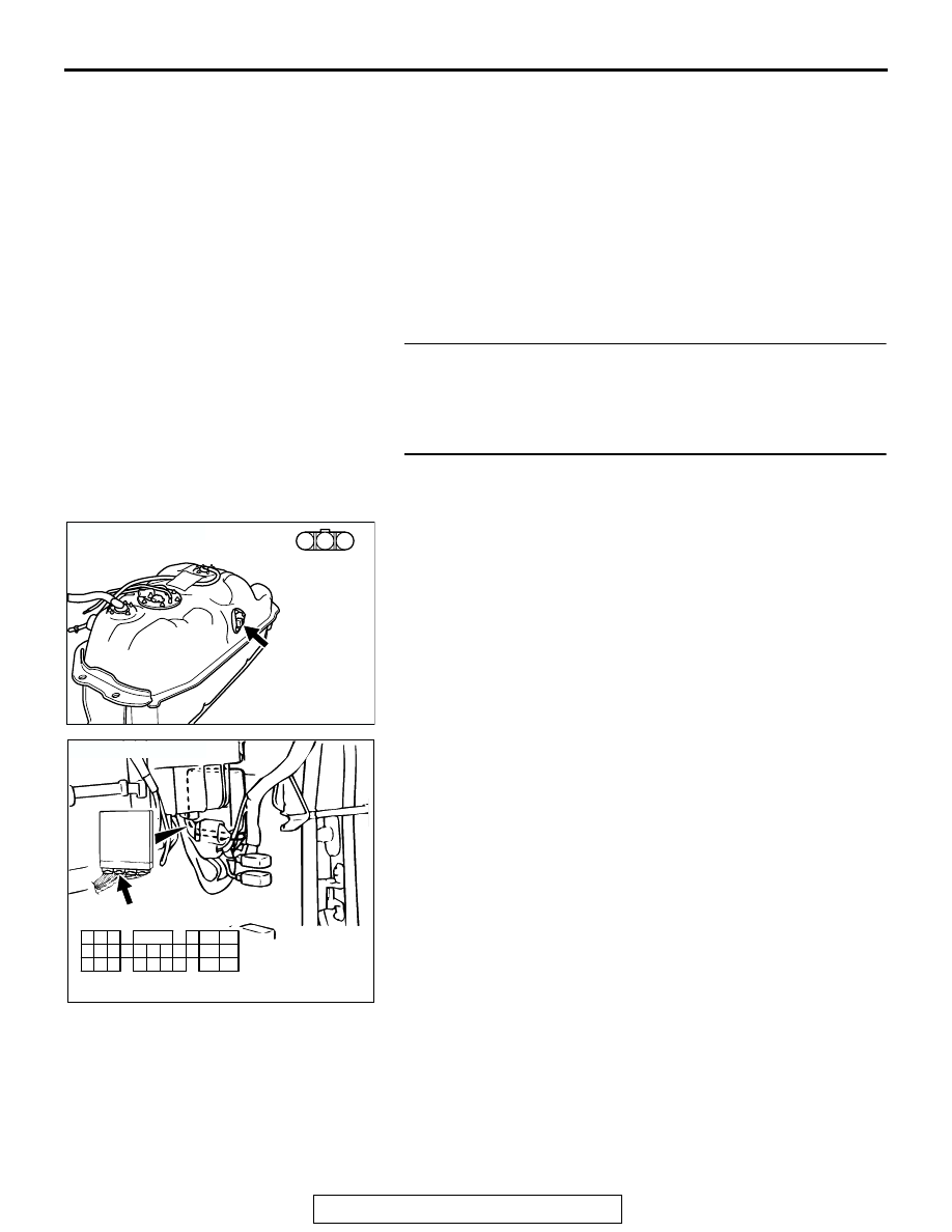
STEP 2. Check for short circuit to ground between fuel 
level sensor connector E-30 (terminal No. 2) and PCM 
connector C-90 (terminal No. 60).

NOTE: Check harness after checking intermediate connectors 
C-85, and E-44. If intermediate connectors are damaged, 
repair or replace them. Refer to GROUP 00E, Harness Con-
nector Inspection 

P.00E-2

. Then go to Step 6.

Q: Is the harness wire in good condition?

YES : Refer to GROUP 54A, Combination Mete

P.54-117

.

NO :  Repair it. Then go to Step 6.

AK200019

3 2 1

CONNECTOR: E-30

AB

HARNESS
CONNECTOR: 
COMPONENT 
SIDE

E-30

AK103762

42

43

48

49

50

51

52

53

54

55

56

57

46 45 44

58

59

60

61

62

63

64

65

66

47

41

AB

CONNECTOR: C-90

C-90(GR)

HARNESS CONNECTOR:
COMPONENT SIDE

MULTIPORT FUEL INJECTION (MFI) DIAGNOSIS

TSB Revision

MULTIPORT FUEL INJECTION (MFI)

13A-638

STEP 3. Check connector C-90 at PCM for damage.
Q: Is the connector in good condition?

YES : Go to Step 4.
NO :  Repair or replace it. Refer to GROUP 00E, Harness 

Connector Inspection 

P.00E-2

. Then go to Step 6.

STEP 4. Check for open circuit or harness damage 
between fuel gauge unit connector E-30 (terminal No. 2) 
and PCM connector C-90 (terminal No. 60).

NOTE: Check harness after checking intermediate connectors 
C-85, and E-44. If intermediate connectors are damaged, 
repair or replace them. Refer to GROUP 00E, Harness Con-
nector Inspection 

P.00E-2

. Then go to Step 6.

Q: Is the harness wire in good condition?

YES : Go to Step 5.
NO :  Repair it. Then go to Step 6.

AK103762

42

43

48

49

50

51

52

53

54

55

56

57

46 45 44

58

59

60

61

62

63

64

65

66

47

41

AB

CONNECTOR: C-90

C-90(GR)

HARNESS CONNECTOR:
COMPONENT SIDE

AK200019

3 2 1

CONNECTOR: E-30

AB

HARNESS
CONNECTOR: 
COMPONENT 
SIDE

E-30

AK103762

42

43

48

49

50

51

52

53

54

55

56

57

46 45 44

58

59

60

61

62

63

64

65

66

47

41

AB

CONNECTOR: C-90

C-90(GR)

HARNESS CONNECTOR:
COMPONENT SIDE

MULTIPORT FUEL INJECTION (MFI) DIAGNOSIS

TSB Revision

MULTIPORT FUEL INJECTION (MFI)

13A-639

STEP 5. Retest the system.
(1) Carry out a test drive with the drive cycle pattern. Refer to 

Diagnostic Function 

− OBD-II Drive Cycle − Procedure 6 − 

Other Monitor 

P.13A-4

.

(2) Check the diagnostic trouble code (DTC).
Q: Is DTC P0461 set?

YES : Replace the PCM. Then go to Step 6.
NO :  It can be assumed that this malfunction is intermittent. 

Refer to GROUP 00, How to Use 
Troubleshooting/Inspection Service Points 

P.00-7

.

STEP 6. Test the OBD-II drive cycle.
(1) Carry out a test drive with the drive cycle pattern. Refer to 

Diagnostic Function 

− OBD-II Drive Cycle − Procedure 6 − 

Other Monitor 

P.13A-4

.

(2) Check the diagnostic trouble code (DTC).
Q: Is DTC P0461 set?

YES :  Repeat the troubleshooting.
NO :  The procedure is complete.

MULTIPORT FUEL INJECTION (MFI) DIAGNOSIS

TSB Revision

MULTIPORT FUEL INJECTION (MFI)

13A-640

DTC P0506: Idle Control System RPM Lower Than Expected 

WHITE-

BLA

CK

WHITE-

BLA

CK

WHITE-

BLA

CK

RED

RED

RED

GREEN-BLA

CK

GREEN-BLUE

GREEN

GREEN-RED

AK200194

Idle Air Control (IAC) Motor Circuit

2

3

4

FUSIBLE LINK (12)

1

12

2

5

17

18

6

4

3

1

MFI
RELAY

14

28

15

29

IDLE AIR
CONTROL
(IAC) MOTOR

POWERTRAIN CONTROL MODULE (PCM)

C-59

1

10

2 3 4 5 6 7 8 9

11

12 13 14 15 16 17 18 19 20 21 22

23 24 25 26 27 28 29 30 31 32 33

C-14

10

2

3 4

5 6

7 8

9

11 12 13 14 15 16 17 18 19 20

30

21 22 23

24

25

26 27 28 29

31 32 33

34 35

1

C-89
(MU803784)

2

4 5 6

3

1

A-40

JOINT
CONNECTOR (5)

1

2

3

4


Content   ..  304  305  306  307   ..