Mitsubishi Montero Sport (2004+). Manual - part 304


  Index      Mitsubishi     Mitsubishi Montero Sport - service repair manual 2004 year


Search            


Content   ..  302  303  304  305   ..


Mitsubishi Montero Sport (2004+). Manual - part 304


MULTIPORT FUEL INJECTION (MFI) DIAGNOSIS

TSB Revision

MULTIPORT FUEL INJECTION (MFI)

13A-629

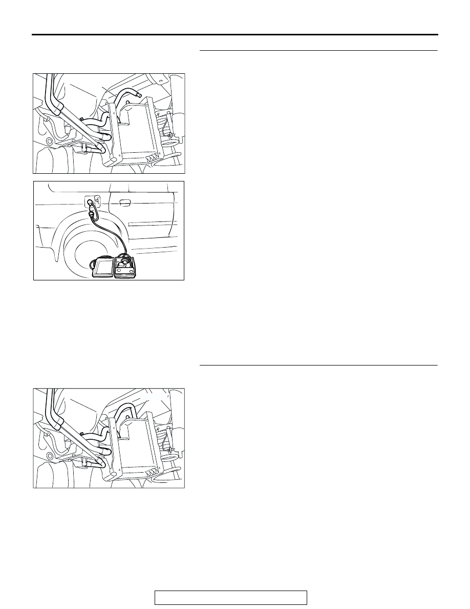
STEP 7. Pressure test the evaporative emission system 
lines from hose E, L and the fuel tank.
(1) Disconnect hose E from the canister side, and plug the 

hose.

(2) Remove the fuel cap.
(3) Confirm that the evaporative emission system pressure 

pump (Miller number 6872A) is operating properly. Perform 
the self-test as described in the manufacturer's instructions.

(4) Connect the evaporative emission system pressure pump 

to the fuel filler neck.

(5) Pressure test the system to determine whether any leaks 

are present.
NOTE: The "Pressure test" in this procedure refers to the 
I/M240 Simulation Test. The eight steps of this test are 
described in the manufacturer's instructions for the evapo-
rative emission system pressure pump, Miller number 
6872A.

(6) After it is confirmed that pressure maintained, unplug hose 

E.

(7) Disconnect the evaporative emission system pressure 

pump, and reinstall the fuel cap.

(8) Connect hose E to the evaporative emission canister.
Q: Is the evaporative emission system line free of leaks?

YES : Go to Step 15 .
NO :  Go to Step 8 .

STEP 8. Check vacuum for leaks in the evaporative 
emission system hose E.
Perform a leakage test with a hand vacuum pump on hose E.
Q: Does the hose N hold vacuum?

YES : Go to Step 9 .
NO :  Replace the damaged hose E. (Refer to GROUP 17, 

Evaporative Emission Canister and Fuel Tank 
Pressure Relief Valve 

P.17-116

). Then go to Step 16 .

AC005140

HOSE E

AC

ACX01358

AC004932

HOSE E

AH

MULTIPORT FUEL INJECTION (MFI) DIAGNOSIS

TSB Revision

MULTIPORT FUEL INJECTION (MFI)

13A-630

STEP 9. Pressure test the leaks in the evaporative 
emission system from hoses H through O.
(1) Remove the fuel filler neck protector. (Refer to GROUP 

13B, Fuel Tank 

P.13B-6

).

(2) Perform a leakage test with a hand vacuum pump on hose 

H through O.

Q: Do the hoses hold vacuum?

YES : Go to Step 10 .
NO :  Replace any damaged hose and reinstall the fuel filler 

neck protector. (Refer to GROUP 13B, Fuel Tank 

P.13B-6

). Then go to Step 16 .

STEP 10. Check the check valve A.
(1) Check valve A is a one-way check valve.
(2) Check valve A should allow air to flow in only one direction.
Q: Does check valve A allow air to flow in one direction 

only?
YES : 
Go to Step 11 .
NO :  Replace check valve A, and reinstall the fuel tank filler 

neck protector. (Refer to GROUP 13B, Fuel Tank 

P.13B-6

). Then go to Step 16 .

STEP 11. Check the check valve B.
(1) Check valve B is an one-way check valve.
(2) Check valve B should allow air to flow in only one direction.
(3) When you blow the check valve, on air should leak from the 

check valve body.

Q: Does check valve B allow air to flow in one direction 

only?
YES : 
Go to Step 12 .
NO :  Replace check valve B, reinstall the fuel filler neck 

protector. (Refer to GROUP 13B, Fuel Tank 

P.13B-6

). 

Then go to Step 16 .

AC004933AD

HOSE I

HOSE G

HOSE H

HOSE J

HOSE F

AC002076 AB

CHECK VALVE A

AC002078

CHECK VALVE B

AB

MULTIPORT FUEL INJECTION (MFI) DIAGNOSIS

TSB Revision

MULTIPORT FUEL INJECTION (MFI)

13A-631

STEP 12. Check for leaks in the evaporative emission 
system line from hose K through L.
(1) Remove the fuel tank. (Refer to GROUP 13B, Fuel Tank 

P.13B-6

).

(2) Perform a leakage test with a hand vacuum pump on each 

hose from hose P through S.

Q: Do the hoses hold vacuum?

YES : Go to Step 13 .
NO :  Replace the damaged hose, and reinstall the fuel 

tank. (Refer to GROUP 13B, Fuel Tank 

P.13B-6

). 

Then go to Step 16 .

STEP 13. Check for leak in the fuel tank.
(1) Visually check for cracks and leaks, etc.

NOTE: Carefully check the fuel pump assembly and the 
inner pressure sensor installation section in the fuel tank.

(2) Connect the evaporative emission system pressure pump 

to the filler hose.

(3) Plug the fuel pump feed nipple, return hose, hose K and 

hose L connected to the fuel tank.
NOTE: If these items are not securely plugged at this time, 
the fuel could leak from the tank.

(4) Pressurize the fuel tank with the evaporative emission 

system pressure pump.

(5) In the pressurized state, check for the leaks by applying 

soapy water solution to each section and look for bubbles.

Q: Are any leaks found?

YES <When there is a leak from the attachment points of 
the fuel pump assembly, the fuel tank differential 
pressure sensor, fuel tank rollover valve.> : 
Reassemble 

the leaked parts and check again that there are no 
leaks. Then reinstall the fuel tank (Refer to GROUP 
13B, Fuel Tank 

P.13B-6

). Then go to Step 16 .

YES <When there is a leak from the fuel tank.> : Replace 

the fuel tank (Refer to GROUP 13B, Fuel Tank 

P.13B-6

). Then go to Step 16 .

NO :  When there is no leak, reinstall the fuel tank (Refer to 

GROUP 13B, Fuel Tank 

P.13B-6

). Then go to Step 14 

.

AC004930

HOSE K

HOSE L

AC

AC005139

AC005138

MULTIPORT FUEL INJECTION (MFI) DIAGNOSIS

TSB Revision

MULTIPORT FUEL INJECTION (MFI)

13A-632

STEP 14. Using scan tool MB991958, check evaporative 
emission system monitor test.

CAUTION

• To prevent damage to scan tool MB991958, always turn 

the ignition switch to the "LOCK" (OFF) position before 
connecting or disconnecting scan tool MB991502.

• During this test, the PCM automatically increases the 

engine speed to 1,600 r/min or greater. Check that the 
transmission is set to "P" position.

(1) Connect scan tool MB991958 to the data link connector.
(2) Turn the ignition switch to the "ON" position.
(3) Erase the DTCs using scan tool MB991958.
(4) Check that the fuel cap is securely closed. (Tighten until 

three clicks are heard).

(5) Start the engine.
(6) Select "System Test" and press the "YES" key.
(7) Select "Evap Leak Mon" and press the "YES" key.
(8) During this test, keep the accelerator pedal at the idling 

position.
NOTE: If the engine speed does not reach 2,000 r/min dur-
ing the monitor test, adjust the Speed Adjusting Screw 
(Refer to 

P.13A-883

), and adjust to the standard value.

(9) Keep the engine speed and engine load within the specified 

range. When the monitor test starts, the "In Progress" item 
on scan tool MB991958 will change from "NO" to "YES".

(10)Turn the ignition switch to the "LOCK" (OFF) position.
Q: Is "Evap Leak Mon. Completed. Test Failed and DTCs 

Set" displayed on scan tool MB991958?
YES : 
Replace the PCM. Then go to Step 16 .
NO <"Evap Leak Mon. Completed. Test Passed" is 
displayed on scan tool MB991958.> : 
The evaporative 

emission system is working properly at this time. Then 
go to Step 16 .

NO <"Evap Leak Mon. Discontinued. Retest again from 
the first" is displayed on scan tool MB991958.> : 
The 

EVAP monitor has been interrupted during the test. 
Turn the ignition switch to the "LOCK" (OFF) position 
once, and repeat the monitor test.

AK303629AB

MB991911

MB991827

MB991824 

16-PIN


Content   ..  302  303  304  305   ..