Mitsubishi Montero Sport (2004+). Manual - part 288


  Index      Mitsubishi     Mitsubishi Montero Sport - service repair manual 2004 year


Search            


Content   ..  286  287  288  289   ..


Mitsubishi Montero Sport (2004+). Manual - part 288


MULTIPORT FUEL INJECTION (MFI) DIAGNOSIS

TSB Revision

MULTIPORT FUEL INJECTION (MFI)

13A-565

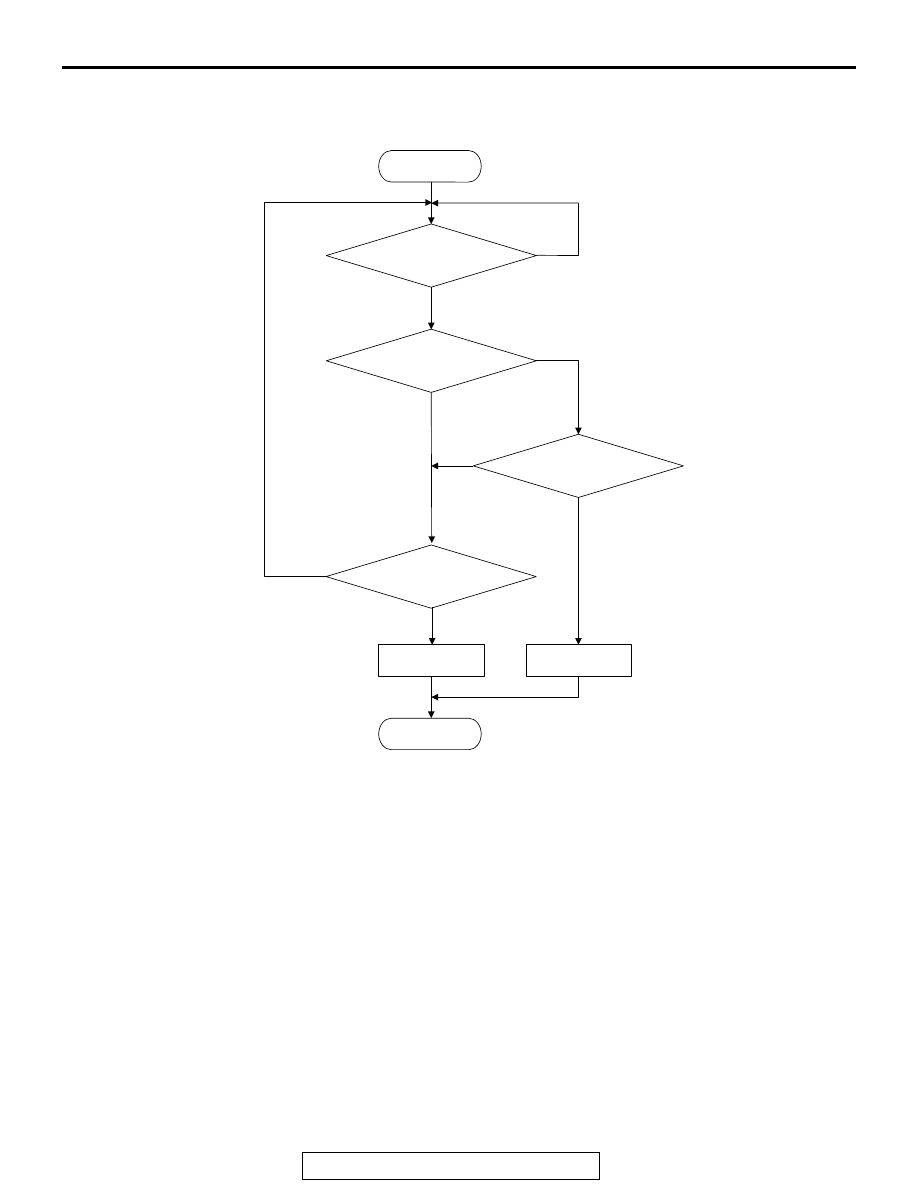
LOGIC FLOW CHARTS (Monitor Sequence)

.

DTC SET CONDITIONS

Test Conditions: For Test to Run

• Intake air temperature is higher than 5°C (41°C).

• Engine speed is 1,600 r/min or more.

• Volumetric efficiency is between 25 and 80 per-

cent.

Judgment Criteria

• When the evaporative emission purge solenoid is 

off, the fuel differential pressure sensor output 
voltage remains 1.0 volt or less for ten seconds.

.

OBD-ll DRIVE CYCLE PATTERN
Refer to Diagnostic Function 

− OBD-ll Drive Cycle − 

Procedure 1 

− Evaporative Emission System Leak 

Monitor 

P.13A-4

.

.

TROUBLESHOOTING HINTS
The most likely causes for this code to be set are:

• Fuel tank differential pressure sensor failed.

• Open fuel tank differential pressure sensor cir-

cuit, or loose connector.

• PCM failed.

.

NO

YES 

CONTINUOUS

FAILURE FOR 10 SECS

START


END


NO 

NO

NO

YES


YES 


YES   

MALFUNCTION

GOOD


MONITORING


CONDITIONS


OUTPUT VOLTAGE


< 1.0V

OUTPUT VOLTAGE


> 4.0V


AC306648

RANGE CHECK - MIN/MAX

MULTIPORT FUEL INJECTION (MFI) DIAGNOSIS

TSB Revision

MULTIPORT FUEL INJECTION (MFI)

13A-566

OVERVIEW OF TROUBLESHOOTING

• The DTC P0452 can be set if either of the follow-

ing conditions occur:

1. Faulty fuel differential pressure sensor, 

related circuit, or PCM.

• To check a system blockage, do a performance 

test which uses a mechanical vacuum gauge and 
scan tool MB991958 set on the fuel tank differen-
tial pressure sensor (TANK PRS SNSR 73.)

The mechanical gauge reading is used to verify 
scan tool MB991958 reading.
A comparison of the mechanical gauge to scan 
tool MB991958 determines the problem in the 
system.

DIAGNOSIS

Required Special Tools:

• MB991958: Scan tool (MUT-III sub assembly)

• MB991824: V.C.I.

• MB991827: MUT-III USB cable

• MB991911: MUT-III main harness B

• MB991658: Test harness set

MULTIPORT FUEL INJECTION (MFI) DIAGNOSIS

TSB Revision

MULTIPORT FUEL INJECTION (MFI)

13A-567

STEP 1. Using scan tool MB991958, check data list item 73: 
Fuel Tank Differential Pressure Sensor.

CAUTION

To prevent damage to scan tool MB991958, always turn the 
ignition switch to the "LOCK" (OFF) position before con-
necting or disconnecting scan tool MB991958.
(1) Connect scan tool MB991958 to the data link connector.

(2) Disconnect hose E from the evaporative emission canister 

side, and plug the hose.

(3) Turn the ignition switch to the "ON" position.
(4) Remove the fuel cap.
(5) Set scan tool MB991958 to the data reading mode.

• Item 73, Fuel Tank Differential Pressure Sensor.

• The fuel tank pressures reading on the scan tool 

should be 

−3.3 to 3.3 kPa (−0.97 to 0.97 inHg).

(6) Connect an evaporative emission system pressure pump to 

the fuel filler neck and pressurize the fuel tank.

• The fuel tank pressure reading should increase.

(7) Turn the ignition switch to the "LOCK" (OFF) position. Then 

disconnect scan tool MB991958.

(8) Disconnect the evaporative emission system pressure 

pump, and reinstall the fuel cap.

(9) Connect hose E to the canister.
Q: Is the fuel tank pressure between 

3.3 and 3.3 kPa 

(

0.97 and 0.97 inHg)?

YES : It can be assumed that this malfunction is intermittent. 

(Refer to GROUP 00, How to Use 
Troubleshooting/Inspection Service Points 

− How to 

Cope with Intermittent Malfunction 

P.00-7

). Then go 

to Step 16 .

NO :  Go to Step 2 .

AK303629AB

MB991911

MB991827

MB991824 

16-PIN

AC005140

HOSE E

AC

ACX01358

MULTIPORT FUEL INJECTION (MFI) DIAGNOSIS

TSB Revision

MULTIPORT FUEL INJECTION (MFI)

13A-568

STEP 2. Measure the sensor output voltage at fuel tank 
differential pressure sensor connector E- 28.
(1) Disconnect hose E from the evaporative emission canister 

side, and plug the hose.

(2) Remove the fuel tank mounting nuts, tilt the fuel tank.

(3) Disconnect fuel tank differential pressure sensor connector 

E-28.

(4) Connect special tool MB991658 between pressure sensor 

connector terminal 1, 2 and 3.

(5) Turn the ignition switch to the "ON" position.
(6) Remove the fuel cap.
(7) Measure the voltage between terminal 1 and ground.

• The measured voltage should measure between 2.0 

and 3.0 volts.

(8) Turn the ignition switch to the "LOCK" (OFF) position.
(9) Disconnect the evaporative emission system pressure 

pump, and reinstall the fuel cap.

(10)Connect hose E to the canister.
Q: Is the measured voltage between 2.0 and 3.0 volts?

YES : Go to Step 7 .
NO :  Go to Step 3 .

AC005140

HOSE E

AC

AC002614

CONNECTOR: E-28

FUEL TANK
DIFFERENTIAL
PRESSURE
SENSOR

AH

E-28 (B)

2 1

3

E-28 HARNESS SIDE 
CONNECTOR

AC002081AB

MB991658

FUEL TANK DIFFERENTIAL 
PRESSURE SENSOR


Content   ..  286  287  288  289   ..