Mitsubishi Montero Sport (2004+). Manual - part 200


  Index      Mitsubishi     Mitsubishi Montero Sport - service repair manual 2004 year


Search            


Content   ..  198  199  200  201   ..


Mitsubishi Montero Sport (2004+). Manual - part 200


MULTIPORT FUEL INJECTION (MFI) DIAGNOSIS

TSB Revision

MULTIPORT FUEL INJECTION (MFI)

13A-213

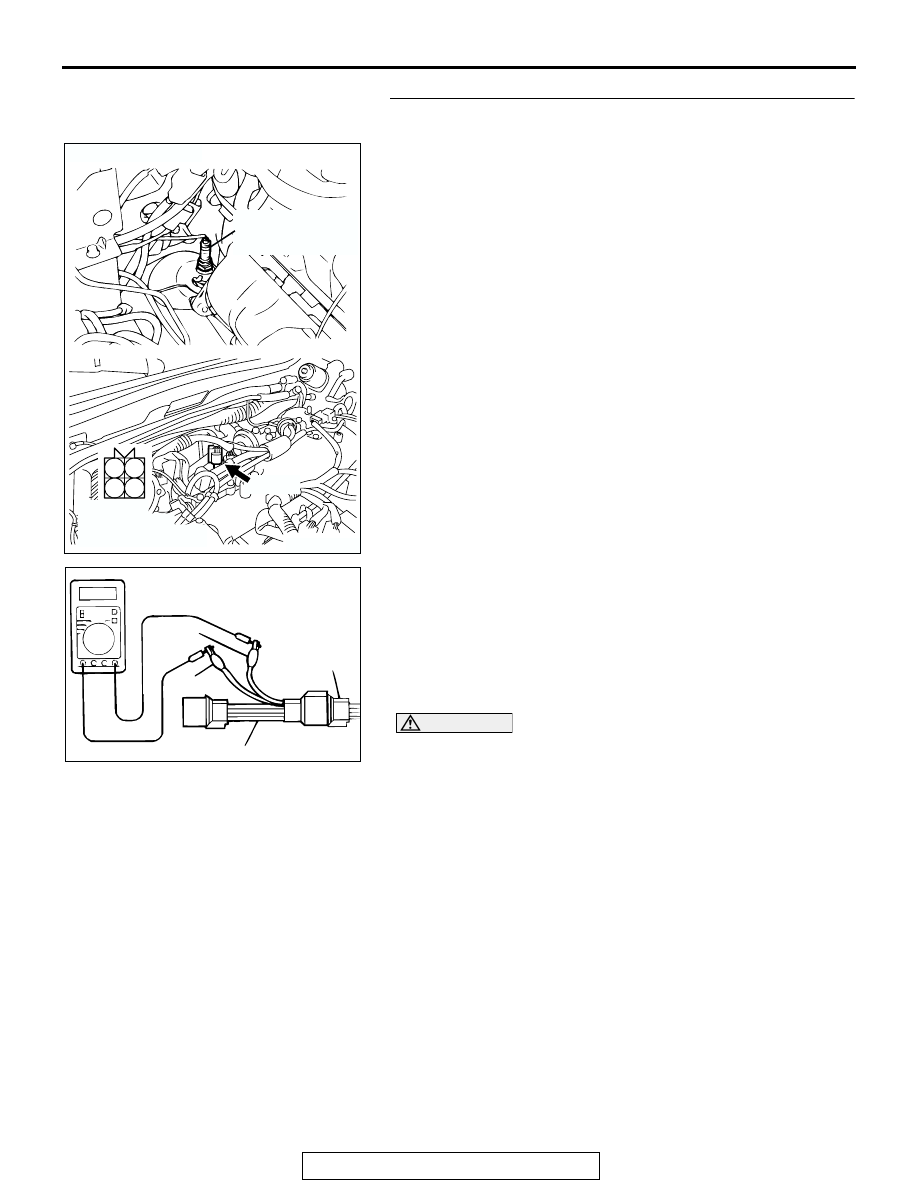
STEP 5. Check the right bank heated oxygen sensor 
(front).
(1) Disconnect the right bank heated oxygen sensor (front) 

connector A-07 and connect test harness special tool, 
MD998464 to the connector on the right bank heated 
oxygen sensor (front) side.

(2) Warm up the engine until engine coolant 80

°C (176°F) or 

higher.

(3) Perform a tracing for 5 minutes or more with the engine 

speed of 4,500 r/min.

(4) Connect a digital volt meter between terminal No. 2 (black 

clip) and terminal No. 4 (white clip).

(5) While repeatedly revving the engine, measure the right 

bank heated oxygen sensor (front) output voltage.

Standard value: 0.6 

 1.0 volt

CAUTION

• Be very careful when connecting the jumper wire; 

incorrect connection can damage the oxygen sensor.

• Be careful the heater is broken when voltage of beyond 

8 volts is applied to the oxygen sensor heater.
NOTE: If the sufficiently high temperature (of approximate 
400

°

C or more) is not reached although the oxygen sensor 

is normal, the output voltage would be possibly low 
although the rich air-fuel ratio. Therefore, if the output volt-
age is low, use a jumper wire to connect the terminal No.1 
(red clip of special tool) and the terminal No. 3 (blue clip of 
special tool) of the oxygen sensor with a (+) terminal and (-) 
terminal of 8 volts power supply respectively, then check 
again.

Q: Is the voltage between 0.6 and 1.0 volt?

YES : Go to Step 6.
NO :  Replace the right bank heated oxygen sensor (front). 

Then go to Step 13.

AK200490

1

2

3

4

A-07(B)

AB

CONNECTOR: A-07

HARNESS 
CONNECTOR: 
COMPONENT SIDE

RIGHT BANK
HEATED OXYGEN
SENSOR (FRONT)

AKX01624

HEATED
OXYGEN
SENSOR
COMPONENT
SIDE
CONNECTOR

MD998464

WHITE

BLACK

AL

MULTIPORT FUEL INJECTION (MFI) DIAGNOSIS

TSB Revision

MULTIPORT FUEL INJECTION (MFI)

13A-214

STEP 6. Check connector A-04 at injector intermediate 
connector for damage.
Q: Is the connector in good condition?

YES : Go to Step 7.
NO :  Repair or replace it. Refer to GROUP 00E, Harness 

Connector Inspection 

P.00E-2

. Then go to Step 13.

STEP 7. Check the right bank injector resistance at 
intermediate connector A-04.
(1) Disconnect the injector intermediate connector A-04.

(2) Measure the resistance between each injector side 

connector terminal.

a. Measure the resistance between terminal No. 3 and No. 

8 when measuring No. 1 cylinder.

b. Measure the resistance between terminal No. 1 and No. 

8 when measuring No. 3 cylinder.

c. Measure the resistance between terminal No. 6 and No. 

8 when measuring No. 5 cylinder.

• Resistance should be between 13 and 16 ohms [at 20°C 

(68

° F)].

Q: Is the resistance normal?

YES : Go to Step 10.
NO :  Go to Step 8.

AK200014

7

2 1
6 5

4 3
8

CONNECTOR: A-04

AB

FEMALE SIDE 
CONNECTOR

A-04(B)

AK200014

7

2 1
6 5

4 3
8

CONNECTOR: A-04

AB

FEMALE SIDE 
CONNECTOR

A-04(B)

AK000452

6

3 4
7 8

1 2
5

INJECTOR
INTERMEDIATE
CONNECTOR

AB

MULTIPORT FUEL INJECTION (MFI) DIAGNOSIS

TSB Revision

MULTIPORT FUEL INJECTION (MFI)

13A-215

STEP 8. Check connector A-73, A-74, A-75 at right bank 
injector for damage.
(1) Remove the intake manifold.
(2) Check the right bank injector connector, which deviates 

from the standard value at Step 7.

Q: Is the connector in good condition?

YES : Go to Step 9.
NO :  Repair or replace it. Refer to GROUP 00E, Harness 

Connector Inspection 

P.00E-2

. Then go to Step 13.

STEP 9. Check the right bank injector.
(1) Check the right bank injector connector, which deviates 

from the standard value at Step 7.

(2) Measure the resistance between injector side connector 

terminal No. 1 and No. 2.

Standard value: 13 

 16 ohms [at 20°C (68°F)]

Q: Is the resistance between 13 and 16 ohms [at 20

°

(68

°F)]?

YES : Repair harness wire between injector intermediate 

connector and right bank injector connector because 
of harness damage. Then go to Step 13.

NO :  Replace the injector. Then go to Step 13.

AK200015

1

2

AB

CONNECTORS: A-73, A-74, A-75

A-73(GR)

A-74(GR)

A-75(GR)

HARNESS CONNECTOR: 
COMPONENT SIDE

AK200015

1

2

AB

CONNECTORS: A-73, A-74, A-75

A-73(GR)

A-74(GR)

A-75(GR)

HARNESS CONNECTOR: 
COMPONENT SIDE

AK000456

1 2

INJECTOR SIDE
CONNECTOR

AB

MULTIPORT FUEL INJECTION (MFI) DIAGNOSIS

TSB Revision

MULTIPORT FUEL INJECTION (MFI)

13A-216

STEP 10. Check connector C-90, C-91 at PCM for damage.
Q: Is the connector in good condition?

YES : Go to Step 11.
NO :  Repair or replace it. Refer to GROUP 00E, Harness 

Connector Inspection 

P.00E-2

. Then go to Step 13.

AK104029

42

43

48

49

50

51

52

53

54

55

56

57

46 45 44

58

59

60

61

62

63

64

65

66

47

41

98

78

71

88

89

76

77

72
79
91

73
80

74

75

81
92

82

83

93

84

85

94

86

87

95

96

90

97

AB

CONNECTORS: C-90, C-91

C-90(GR) C-91(GR)

C-90 HARNESS CONNECTOR:
COMPONENT SIDE

C-91 HARNESS CONNECTOR:
COMPONENT SIDE


Content   ..  198  199  200  201   ..