Mitsubishi Montero Sport (2004+). Manual - part 179
MULTIPORT FUEL INJECTION (MFI) DIAGNOSIS
TSB Revision
MULTIPORT FUEL INJECTION (MFI)
13A-129
.
CIRCUIT OPERATION
• 5-volt voltage is applied to the engine coolant
temperature sensor output terminal (terminal No.
1) from the PCM (terminal No. 44) via the resistor
in the PCM. The ground terminal (terminal No. 2)
is grounded with (terminal No. 57).
• The engine coolant temperature sensor is a neg-
ative temperature coefficient type of resistor. It
has the characteristic that when the engine cool-
ant temperature rises the resistor decreases.
• The engine coolant temperature sensor output
voltage increases when the resistor increases
and decreases when the resistor decreases.
.
TECHNICAL DESCRIPTION
• The engine coolant temperature sensor converts
the engine coolant temperature to a voltage and
output it.
• The PCM checks whether this voltage is within a
specified range.
.
DESCRIPTIONS OF MONITOR METHODS
Engine coolant temperature sensor output voltage is
out of specified range.
.
MONITOR EXECUTION
Continuous
.
MONITOR EXECUTION CONDITIONS (Other
monitor and Sensor)
Other Monitor (There is no temporary DTC stored
in memory for the item monitored below)
• Not applicable
Sensor (The sensor below is determined to be
normal)
• Not applicable
.
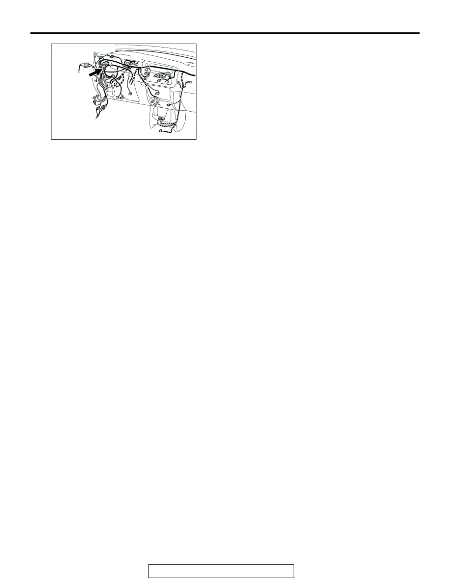
AK103912AB
CONNECTOR: C-71
C-71