Mitsubishi Montero Sport (2004+). Manual - part 172


  Index      Mitsubishi     Mitsubishi Montero Sport - service repair manual 2004 year


Search            


Content   ..  170  171  172  173   ..


Mitsubishi Montero Sport (2004+). Manual - part 172


MULTIPORT FUEL INJECTION (MFI) DIAGNOSIS

TSB Revision

MULTIPORT FUEL INJECTION (MFI)

13A-101

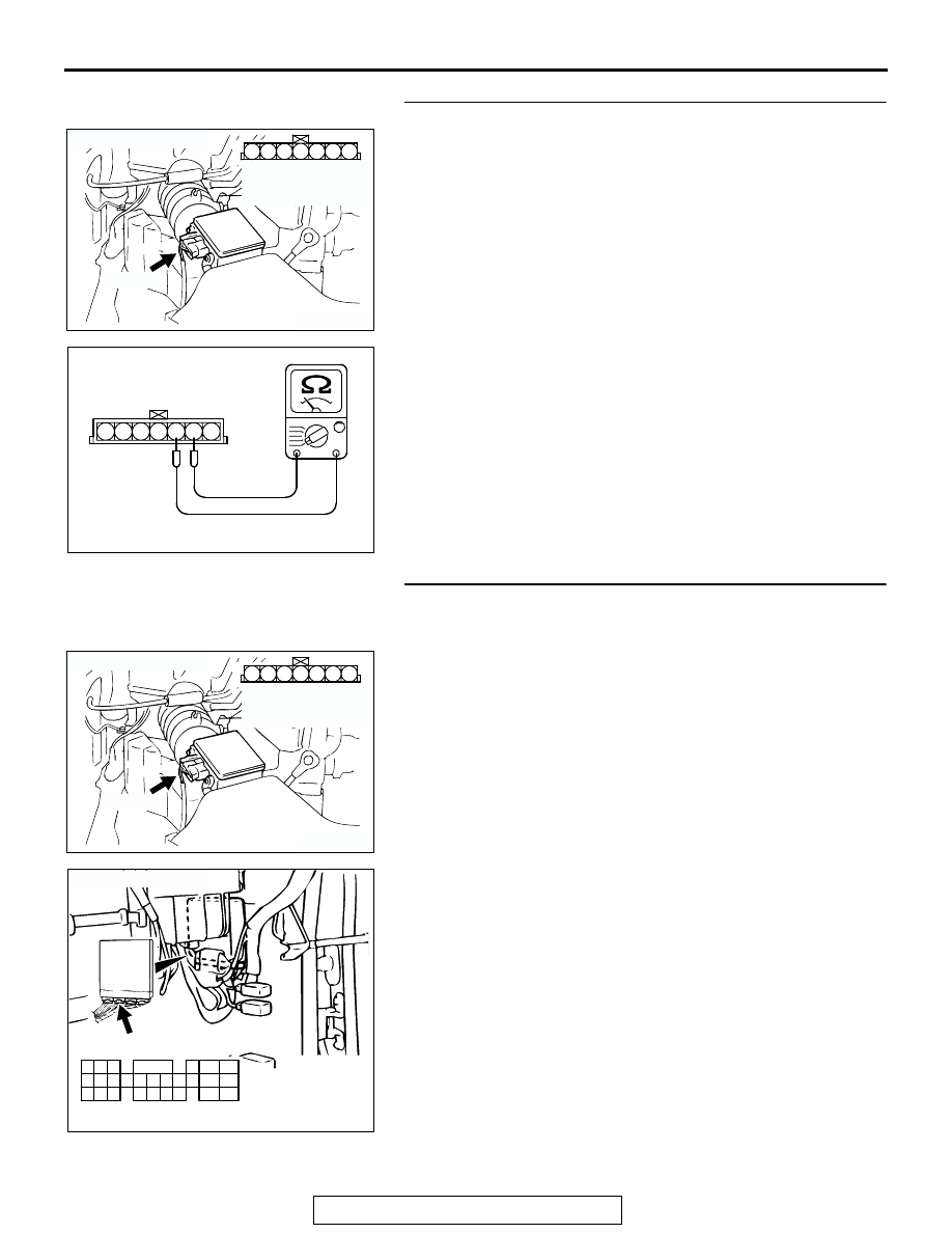
STEP 3. Check the intake air temperature sensor.
(1) Disconnect the intake air temperature sensor connector 

A-01.

(2) Measure the resistance between intake air temperature 

sensor side connector terminal No. 5 and No. 6.

• There should be continuity. (0.30 − 20 kΩ)

Q: Is the measured resistance between 0.3 and 20 k

?

YES : Go to Step 4.
NO :  Replace the volume airflow sensor. Then go to Step 6.

STEP 4. Check for short circuit to ground between intake 
air temperature sensor connector A-01 (terminal No. 6) and 
PCM connector C-90 (terminal No. 64).
Q: Is the harness wire in good condition?

YES : Go to Step 5.
NO :  Repair it. Then go to Step 6.

AK103913

3

4

5

1

2

6

7

CONNECTOR: A-01

A-01(B)

AB

HARNESS 
CONNECTOR: 
COMPONENT SIDE

AK000319AB

1 2 3 4 5 6 7

INTAKE AIR TEMPERATURE
SENSOR SIDE CONNECTOR

AK103913

3

4

5

1

2

6

7

CONNECTOR: A-01

A-01(B)

AB

HARNESS 
CONNECTOR: 
COMPONENT SIDE

AK103762

42

43

48

49

50

51

52

53

54

55

56

57

46 45 44

58

59

60

61

62

63

64

65

66

47

41

AB

CONNECTOR: C-90

C-90(GR)

HARNESS CONNECTOR:
COMPONENT SIDE

MULTIPORT FUEL INJECTION (MFI) DIAGNOSIS

TSB Revision

MULTIPORT FUEL INJECTION (MFI)

13A-102

STEP 5. Check connector C-90 at PCM for damage.
Q: Is the connector in good condition?

YES : Replace the PCM. Then go to Step 6.
NO :  Repair or replace it. Refer to GROUP 00E, Harness 

Connector Inspection 

P.00E-2

. Then go to Step 6.

STEP 6. Test the OBD-II drive cycle.
(1) Carry out a test drive with the drive cycle pattern. Refer to 

Diagnostic Function 

− OBD-II Drive Cycle − Procedure 6 − 

Other Monitor 

P.13A-4

.

(2) Check the diagnostic trouble code (DTC).
Q: Is DTC P0112 set?

YES : Repeat the troubleshooting.
NO :  The procedure is complete.

AK103762

42

43

48

49

50

51

52

53

54

55

56

57

46 45 44

58

59

60

61

62

63

64

65

66

47

41

AB

CONNECTOR: C-90

C-90(GR)

HARNESS CONNECTOR:
COMPONENT SIDE

MULTIPORT FUEL INJECTION (MFI) DIAGNOSIS

TSB Revision

MULTIPORT FUEL INJECTION (MFI)

13A-103

DTC P0113: Intake air temperature Circuit High Input

AK301863

Intake Air Temperature Sensor Circuit

RED

-BL

UE

BL

ACK

BL

ACK

57

5

5V

POWERTRAIN CONTROL MODULE (PCM)

INTAKE AIR TEMPERATURE SENSOR
(INCORPORATED IN VOLUME 
AIRFLOW SENSOR)

12

6

64

15

1 2 3 4 5 6 7

A-01

1

10

2 3 4 5 6 7 8 9

11

12 13 14 15 16 17 18 19 20 21 22

23 24 25 26 27 28 29 30 31 32 33

C-71

47

41

42 43

48 49 50 51 52 53 54 55 56 57

46

45

44

58

59

60 61 62 63

64 65 66

C-90
(MU803781)

JOINT
CONNEC-
TOR (4)

AK103908

CONNECTOR: A-01

INTAKE AIR 
TEMPERATURE
SENSOR

A-01(B)

AD

AK103738AC

CONNECTOR: C-90

PCM

C-90(GR)

MULTIPORT FUEL INJECTION (MFI) DIAGNOSIS

TSB Revision

MULTIPORT FUEL INJECTION (MFI)

13A-104

.

CIRCUIT OPERATION

• Approximately 5 volts are applied to the intake air 

temperature sensor output terminal (terminal No. 
6) from the PCM (terminal No. 64) via the resistor 
in the PCM. The ground terminal (terminal No. 5) 
is grounded with PCM (terminal No. 57).

• The intake air temperature sensor is a negative 

temperature coefficient type of resistor. When the 
intake air temperature rises, the resistance 
decreases.

• The intake air temperature sensor output voltage 

increases when the resistance increases and 
decreases when the resistance decreases.

.

TECHNICAL DESCRIPTION

• The intake air temperature sensor converts the 

intake air temperature to a voltage.

• The PCM checks whether this voltage is within a 

specified range.

.

DESCRIPTIONS OF MONITOR METHODS
Intake air temperature sensor output voltage is out of 

specified range.

.

MONITOR EXECUTION
Continuous

.

MONITOR EXECUTION CONDITIONS (Other 
monitor and Sensor)

Other Monitor (There is no temporary DTC stored 

in memory for the item monitored below)

• Not applicable

Sensor (The sensor below is determined to be 

normal)

• Not applicable

.

AK103912AB

CONNECTOR: C-71

C-71


Content   ..  170  171  172  173   ..