Mitsubishi Montero Sport (2004+). Manual - part 160


  Index      Mitsubishi     Mitsubishi Montero Sport - service repair manual 2004 year


Search            


Content   ..  158  159  160  161   ..


Mitsubishi Montero Sport (2004+). Manual - part 160


MULTIPORT FUEL INJECTION (MFI) DIAGNOSIS

TSB Revision

MULTIPORT FUEL INJECTION (MFI)

13A-53

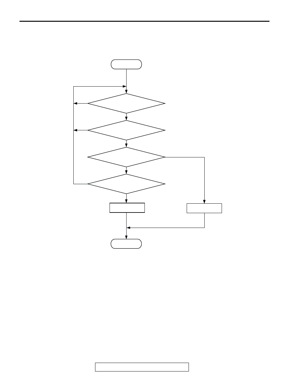
DTC SET CONDITIONS <Range/Performance problem-high input>

Logic Flow Chart

.

Check Conditions

• 8 minutes or more have passed since the starting 

sequence was completed, when the engine cool-
ant temperature at engine start is 0

°C (32°F) or 

lower.

• Engine speed is lower than 1,500 r/min.

• Throttle position sensor output voltage is lower 

than 0.9 volt.

Judgement Criteria

• Manifold Absolute pressure is 89 kPa (26.3 

in.Hg) or higher for 2 seconds.

.

START

YES

YES

YES

YES

NO

NO

NO

NO

MONITORING

CONDITIONS

PRESSURE > 89kPa (26.3in.Hg)

CONTINUOUS

FAILURE FOR 2secs

MALFUNCTION

END

GOOD

THROTTLE POSITION < =0.9V

AK301414

MULTIPORT FUEL INJECTION (MFI) DIAGNOSIS

TSB Revision

MULTIPORT FUEL INJECTION (MFI)

13A-54

DTC SET CONDITIONS <Range/Performance problem-low input>

Logic Flow Chart

.

Check Conditions

• 8 minutes or more have passed since the starting 

sequence was completed, when the engine cool-
ant temperature at engine start is 0

°C (32°F) or 

lower.

• Engine speed is higher than 1,500 r/min.

• Throttle position sensor output voltage is higher 

than 3.5 volts.

Judgement Criteria

• Manifold Absolute pressure is 45 kPa (13.3 

in.Hg) or lower for 2 seconds.

.

OBD-II DRIVE CYCLE PATTERN
Refer to Diagnostic Function 

− OBD-II Drive Cycle − 

Procedure 6 

− Other Monitor 

P.13A-4

.

.

TROUBLESHOOTING HINTS (The most likely 
causes for this code to be set are: )

• Manifold absolute pressure sensor failed.

• Open or shorted manifold absolute pressure sen-

sor circuit, harness damage or connector dam-
age.

• PCM failed.

START

YES

YES

YES

YES

NO

NO

NO

NO

MONITORING

CONDITIONS

PRESSURE < 

45kPa (13.3in.Hg)

CONTINUOUS

FAILURE FOR 2secs

MALFUNCTION

END

GOOD

THROTTLE POSITION > =3.5V

AK303234

MULTIPORT FUEL INJECTION (MFI) DIAGNOSIS

TSB Revision

MULTIPORT FUEL INJECTION (MFI)

13A-55

DIAGNOSIS

Required Special Tools:

• MB991958: Scan Tool (MUT-III Sub Assembly)

• MB991824: V.C.I.

• MB991827: USB Cable

• MB991911: Main Harness B

STEP 1. Using scan tool MB991958, check data list item 95: 
Manifold Absolute Pressure Sensor.

CAUTION

To prevent damage to scan tool MB991958, always turn the 
ignition switch to the "LOCK" (OFF) position before con-
necting or disconnecting scan tool MB991958.
(1) Connect scan tool MB991958 to the data link connector.
(2) Turn the ignition switch to the "ON" position.
(3) Set scan tool MB991958 to the data reading mode for item 

95, Manifold Absolute Pressure Sensor.

• When altitude is 0 m (0 feet), 101 kPa (29.8 in.Hg).

• When altitude is 600 m (1,969 feet), 95 kPa (28.1 in.Hg).

• When altitude is 1,200 m (3,937 feet), 88 kPa (26.0 

in.Hg).

• When altitude is 1,800 m (5,906 feet), 81 kPa (23.9 

in.Hg).

(4) Start the engine.

• When the engine is idling, 16 − 36 kPa (4.7 − 10.6 

in.Hg).

• When the engine is suddenly revved, manifold absolute 

pressure increases.

(5) Turn the ignition switch to the "LOCK" (OFF) position.
Q: Is the sensor operating properly?

YES : It can be assumed that this malfunction is intermittent. 

Refer to GROUP 00, How to Use 
Troubleshooting/Inspection Service Points 

P.00-7

.

NO :  Go to Step 2.

AK303629AB

MB991911

MB991827

MB991824 

16-PIN

MULTIPORT FUEL INJECTION (MFI) DIAGNOSIS

TSB Revision

MULTIPORT FUEL INJECTION (MFI)

13A-56

STEP 2. Measure the sensor supply voltage at manifold 
absolute pressure sensor connector A-12 by backprobing.
(1) Do not disconnect the connector A-12.
(2) Turn the ignition switch to the "ON" position.

(3) Measure the voltage between terminal No. 3 and ground by 

backprobing.

• Voltage should be between 4.8 and 5.2 volts.

(4) Turn the ignition switch to the "LOCK" (OFF) position.
Q: Is the measured voltage between 4.8 and 5.2 volts?

YES : Go to Step 6.
NO :  Go to Step 3.

STEP 3. Measure the sensor supply voltage at PCM 
connector C-90 by backprobing.
(1) Do not disconnect the connector C-90.
(2) Turn the ignition switch to the "ON" position.
(3) Measure the voltage between terminal No. 46 and ground 

by backprobing.

• Voltage should be between 4.8 and 5.2 volts.

(4) Turn the ignition switch to the "LOCK" (OFF) position.
Q: Is the measured voltage between 4.8 and 5.2 volts?

YES : Go to Step 4.
NO :  Go to Step 5.

AK200034

2 1

3

AB

CONNECTOR: A-12

A-12(B)

HARNESS 
CONNECTOR:
COMPONENT 
SIDE

3

2

1

AK203036

A-12 HARNESS 
CONNECTOR: 
HARNESS SIDE

AF

AK103762

42

43

48

49

50

51

52

53

54

55

56

57

46 45 44

58

59

60

61

62

63

64

65

66

47

41

AB

CONNECTOR: C-90

C-90(GR)

HARNESS CONNECTOR:
COMPONENT SIDE

AK000284 AM

<A/T>

C-90 HARNESS 
CONNECTOR: 
HARNESS SIDE

41 42 43

44 45 46

47 48 49 50 51 52 53 54 55 56 57
58 59

60 61 62 63

64 65 66


Content   ..  158  159  160  161   ..