Mitsubishi Montero Sport (2004+). Manual - part 139
CYLINDER HEAD AND VALVES
TSB Revision
ENGINE OVERHAUL
11B-31
INSPECTION
M1113007000022
.
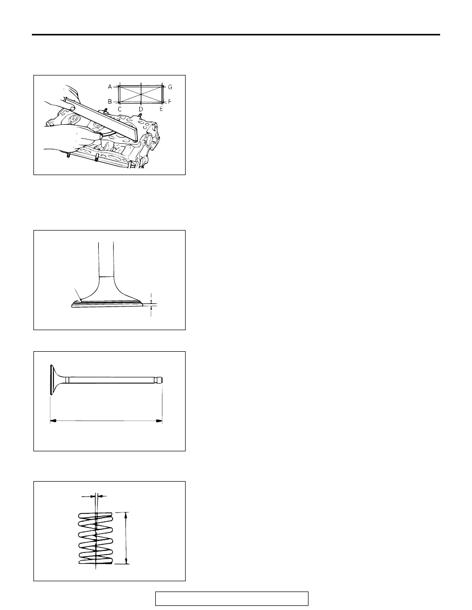
CYLINDER HEAD
1. Check the cylinder head gasket surface for flatness by using
a straightedge in the directions of A through G shown in the
illustration.
Standard value: 0.03 mm (0.0012 inch)
Limit: 0.2 mm (0.007 inch)
2. If the service limit is exceeded, correct to meet the
specification.
Grinding limit: *0.2 mm (0.007 inch)
3. *If the service limit is exceeded, correct to meet the
specification.
Cylinder head height (specification when new):
120 mm (4.7 inches)
.
VALVE
1. Check the valve face for correct contact. If incorrect, reface
using a valve refacer. The valve should make a uniform
contact with the seat at the center of the valve face.
2. If the margin exceeds the service minimum limit, replace the
valve.
Standard value:
<Intake> 1.0 mm (0.04 inch)
<Exhaust> 1.2 mm (0.05 inch)
Minimum limit:
<Intake> 0.5 mm (0.02 inch)
<Exhaust> 0.7 mm (0.03 inch)
3. Measure the valve's total length. If the measurement is less
than specified, replace the valve.
Standard value:
<Intake> 112.30 mm (4.421 inches)
<Exhaust> 114.11 mm (4.493 inches)
Minimum limit:
<Intake> 111.80 mm (4.402 inches)
<Exhaust> 113.61 mm (4.473 inches)
.
VALVE SPRINGS
1. Measure the free height of the spring and, if it is smaller than
the minimum limit, replace the spring.
Standard value: 51.0 mm (2.01 inches)
Minimum limit: 50.0 mm (1.97 inches)
2. Measure the squareness of the spring and, if the limit is
exceeded, replace the spring.
Standard value: 2
° or less
Limit: 4
°
AKX00733
AKX00619
MARGIN
VALVE SEAT
CONTACT
AB
AKX00624
AKX00607
2˚
FREE
HEIGHT
AB