Mitsubishi Montero Sport (2004+). Manual - part 117
AUTO-CRUISE CONTROL
TSB Revision
ENGINE AND EMISSION CONTROL
17-63
.
CIRCUIT OPERATION
This is the stoplight switch input signal circuit.
The signal is sent to the stoplight switch from fuse 9,
and is then sent to the auto-cruise control-ECU.
.
TECHNICAL DESCRIPTION (COMMENT)
The cause is probably a malfunction of the stoplight
switch circuit.
.
TROUBLESHOOTING HINTS
• Malfunction of the stoplight switch.
• Damaged harness or connector.
• Malfunction of the auto-cruise control-ECU.
AC004767
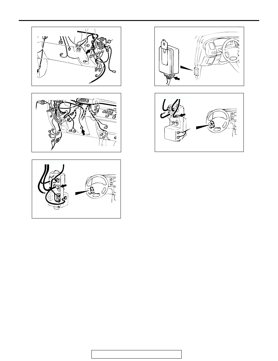
CONNECTOR: C-10
AC
C-10
AC004747 AC
CONNECTOR: C-35
C-35 (B)
AC004751 AJ
CONNECTOR: C-66
C-66 (B)
AC004769 AC
JUNCTION BLOCK
(FRONT)
CONNECTOR: D-02
D-02 (GR)
AC004768
JUNCTION BLOCK
(REAR)
CONNECTOR: D-09
AC
D-09