Mitsubishi Montero Sport (2004+). Manual - part 115
AUTO-CRUISE CONTROL
TSB Revision
ENGINE AND EMISSION CONTROL
17-55
.
CIRCUIT OPERATION
Power of the auto-cruise control-ECU is transmitted
from the ignition switch (IG1) to the auto-cruise con-
trol-ECU through fuse 8 in the junction block.
.
TECHNICAL DESCRIPTION (COMMENT)
The cause is probably a malfunction of the
auto-cruise control-ECU power supply circuit or the
auto-cruise control-ECU ground circuit.
.
TROUBLESHOOTING HINTS
• Damaged harness or connector
• Malfunction of the auto-cruise control-ECU
AC004747 AC
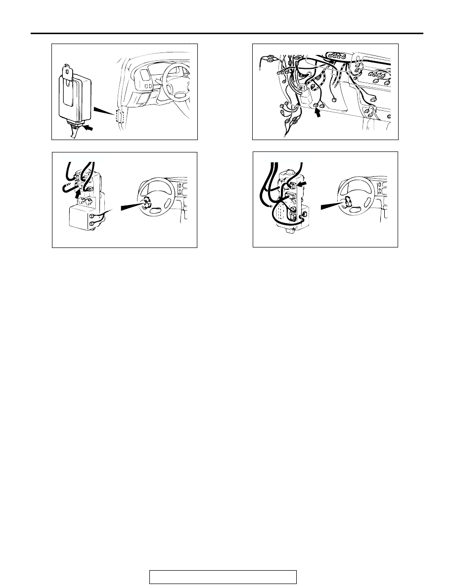
CONNECTOR: C-35
C-35 (B)
AC004751 AO
CONNECTOR: C-69
C-69 (B)
AC004763
JUNCTION BLOCK
(FRONT)
CONNECTOR: D-06
AC
D-06
AC004764 AC
JUNCTION BLOCK
(REAR)
CONNECTOR: D-08
D-08