Mitsubishi Montero Sport (2004+). Manual - part 108


  Index      Mitsubishi     Mitsubishi Montero Sport - service repair manual 2004 year


Search            


Content   ..  106  107  108  109   ..


Mitsubishi Montero Sport (2004+). Manual - part 108


AUTO-CRUISE CONTROL

TSB Revision

ENGINE AND EMISSION CONTROL

17-27

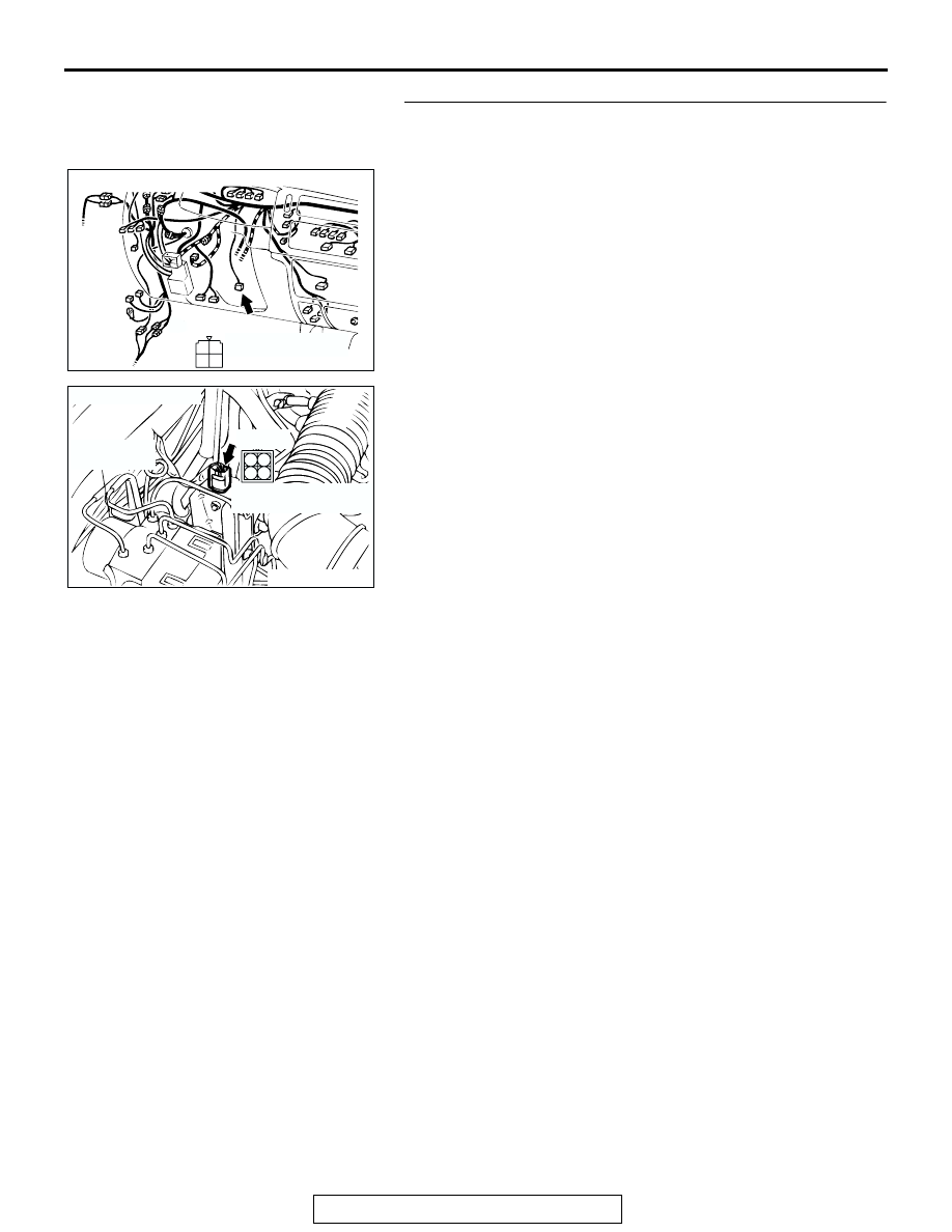
STEP 8. Check the harness wire between stoplight switch 
connector C-66 (terminal No.1) and auto-cruise control 
vacuum pump connector A-02 (Terminal No.1).
Q: Is any harness wire between stoplight switch connector 

C-66 and auto-cruise control vacuum pump connector 
A-02 damaged?
YES : 
Repair or replace the harness wire. Then go to Step 

19 .

NO :  It can be assumed that this malfunction is intermittent. 

(Refer to GROUP 00, How to Use 
Troubleshooting/Inspection Service Points 

− How to 

Cope with Intermittent Malfunction 

P.00-7

).

AC202157

1
3

4

2

CONNECTOR: C-66

AB

C-66 (B)

C-66:HARNESS SIDE 
CONNECTOR

AC202156

3

1 2

4

CONNECTOR:A-02

HYDRAULIC
UNIT

AB

A-02:HARNESS SIDE 
CONNECTOR

A-02 (B)

AUTO-CRUISE CONTROL

TSB Revision

ENGINE AND EMISSION CONTROL

17-28

STEP 9. Measure the output circuit voltage at auto-cruise 
control-ECU connector C-35 by backprobing.
(1) Do not disconnect auto-cruise control-ECU connector C-35.
(2) Turn the ignition switch to the "ON" position and the 

auto-cruise control main switch to the "ON" position.

(3) Measure the voltage between auto-cruise control-ECU 

connector C-35 terminal 7 and ground by backprobing.

• Voltage should measure battery positive voltage. [When 

decelerating with the "SET" switch while driving at con-
stant speed (Release valve open).]

(4) Measure the voltage between auto-cruise control-ECU 

connector C-35 terminal 8 and ground by backprobing.

• Voltage should measure battery positive voltage. [When 

decelerating with the "SET" switch while driving at con-
stant speed. (Control valve open).]

(5) Measure the voltage between auto-cruise control-ECU 

connector C-35 terminal 16 and ground by backprobing.

• Voltage should measure battery positive voltage. (When 

the motor is stopped during a constant road speed.)

(6) Turn the ignition switch to the "LOCK" (OFF) position.
Q: Are all of the above values satisfied?

YES : Go to Step 18 
NO :  Go to Step 10 .

AC202155

2

3

10

11

5

6

13

14

12

4

8

16 15

7

9

1

C-35 (B)

AB

CONNECTOR: C-35

C-35 HARNESS SIDE 
CONNECTOR

1 2 3 4 5 6 7 8

9 10 11 12 13 14 15 16

ACX01897

C-35 HARNESS CONNECTOR:
HARNESS SIDE

AJ

AUTO-CRUISE CONTROL

TSB Revision

ENGINE AND EMISSION CONTROL

17-29

STEP 10. Check auto-cruise control-ECU connector C-35 
and intermediate connector C-41 for loose, corroded or 
damaged terminals, or terminals pushed back in the 
connector.
Q: Is the connector damaged?

YES : Repair or replace the damaged components. (Refer 

to GROUP 00E, Harness Connector Inspection 

P.00E-2

). Then go to Step 19 .

NO :  Go to Step 11 .

STEP 11. Check auto-cruise control vacuum pump 
connector A-02 for loose, corroded or damaged terminals, 
or terminals pushed back in the connector.
Q: Is the connector damaged?

YES : Repair or replace the damaged components. (Refer 

to GROUP 00E, Harness Connector Inspection 

P.00E-2

). Then go to Step 19 .

NO :  Go to Step 12 .

AC202155

2

3

10

11

5

6

13

14

12

4

8

16 15

7

9

1

C-35 (B)

AB

CONNECTOR: C-35

C-35 HARNESS SIDE 
CONNECTOR

AC202075

22

2021

10

9

8

1718

6 7

19

1415

4 5

1112

1 2 3

13

16

CONNECTOR: C-41

AB

C-41

C-41: MALE SIDE CONNECTOR

AC202156

3

1 2

4

CONNECTOR:A-02

HYDRAULIC
UNIT

AB

A-02:HARNESS SIDE 
CONNECTOR

A-02 (B)

AUTO-CRUISE CONTROL

TSB Revision

ENGINE AND EMISSION CONTROL

17-30

STEP 12. Check the auto-cruise vacuum pump.
(1) Disconnect the vacuum hose from the auto-cruise vacuum 

pump and connect a vacuum gauge to the vacuum pump.

(2) Disconnect the vacuum pump connector A-02.

(3) Check the auto-cruise vacuum pump and valves according 

to the following procedure:

• Connect the positive battery terminal to auto-cruise vac-

uum pump connector A-02 terminal 1, and the negative 
battery terminal to terminals 2, 3, and 4. The vacuum 
gauge should read 27 kPa (8.0 in Hg) or more.

• The vacuum should be maintained when auto-cruise 

vacuum pump connector A-02 terminal 4 is discon-
nected from the negative battery terminal while termi-
nals 1, 2, and 3 remain connected. Then the vacuum 
gauge should read 0 kPa (0 in Hg) when terminal 2 is 
disconnected from the negative battery terminal while 
terminals 1, and 3 remain connected.

• The vacuum should be maintained when auto-cruise 

vacuum pump connector A-02 terminal 4 is discon-
nected from the negative battery terminal while termi-
nals 1, 2, and 3 remain connected. Then the vacuum 
gauge should read 0 kPa (0 in Hg) when terminal 3 is 
disconnected from the negative battery terminal while 
terminals 1, and 2 remain connected.

Q: Are all of the above values satisfied?

YES : Go to Step 13 .
NO :  Replace the auto-cruise vacuum pump. (Refer to 

P.17-99

). Then go to Step 19 .

AC202156

3

1 2

4

CONNECTOR:A-02

HYDRAULIC
UNIT

AB

A-02:HARNESS SIDE 
CONNECTOR

A-02 (B)

AC004749 AD

VACUUM GAUGE

A-02
HARNESS CONNECTOR:
AUTO-CRUISE VACUUM
PUMP SIDE


Content   ..  106  107  108  109   ..