Mitsubishi Montero Sport (2004+). Manual - part 107


  Index      Mitsubishi     Mitsubishi Montero Sport - service repair manual 2004 year


Search            


Content   ..  105  106  107  108   ..


Mitsubishi Montero Sport (2004+). Manual - part 107


AUTO-CRUISE CONTROL

TSB Revision

ENGINE AND EMISSION CONTROL

17-23

CIRCUIT OPERATION
This circuit supplies the power to the vacuum pump. 
The battery positive voltage is supplied to the 
auto-cruise control vacuum pump by turning on the 
transistor at terminal number 16 of the auto-cruise 
control-ECU. 
The conditions for turning on the transistor at termi-
nal number 16 of the auto-cruise control-ECU are as 
follows.

• Ignition switch "ON"

• Auto-cruise control main switch "ON"

• Stoplight switch ON

.

DTC SET CONDITIONS
None of the drive signals from release valve, control 
valve and motor of the auto-cruise vacuum pump are 
input to the auto-cruise control-ECU.

.

TROUBLESHOOTING HINTS
The most likely causes for this code to be set are:

• Malfunction of the stoplight switch

• Malfunction of the auto-cruise vacuum pump

• Damaged harness or connector.

• Malfunction of the auto-cruise control-ECU

DIAGNOSIS

Required Special Tool:

• MB991223: Harness set

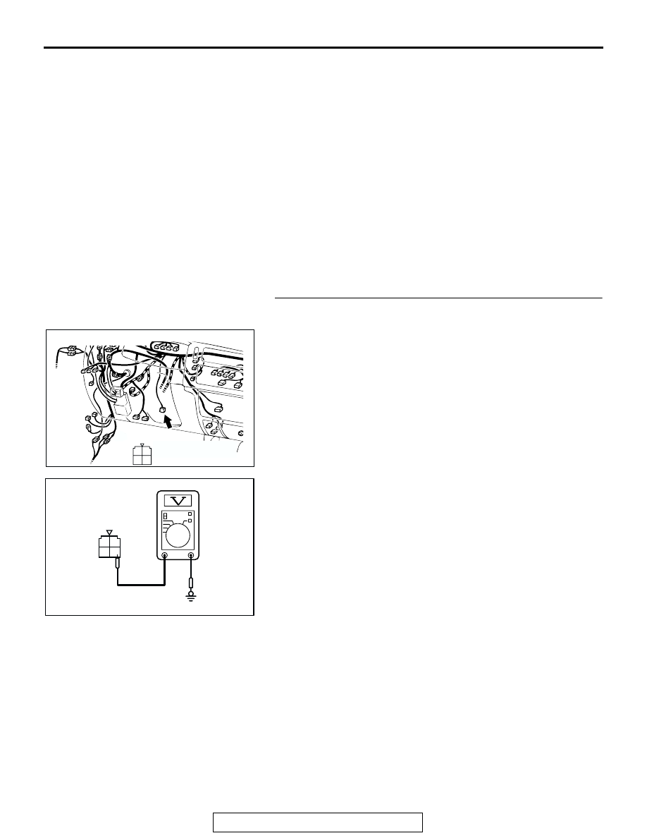
STEP 1. Measure the output circuit voltage at stoplight 
switch connector C-66 by backprobing.
(1) Do not disconnect stoplight switch connector C-66.
(2) Turn the ignition switch to the "ON" position.

(3) Measure the voltage between stoplight switch connector 

C-66 terminal 4 and ground by backprobing.

• The measured voltage should measure battery positive 

voltage. (When brake pedal is depressed).

• The measured voltage should measure 0 V. (When 

brake pedal is not depressed). 

(4) Turn the ignition switch to the "LOCK" (OFF) position.
Q: Are all of the measured voltage satisfied?

YES : Go to Step 3 .
NO :  Go to Step 2 .

AC202157

1
3

4

2

CONNECTOR: C-66

AB

C-66 (B)

C-66:HARNESS SIDE 
CONNECTOR

1 2
3 4

AC103615AC

C-66 HARNESS CONNECTOR:
HARNESS SIDE

AUTO-CRUISE CONTROL

TSB Revision

ENGINE AND EMISSION CONTROL

17-24

STEP 2. Check stoplight switch connector C-66 for loose, 
corroded or damaged terminals, or terminals pushed back 
in the connector.
Q: Is the connector damaged?

YES : Repair or replace the damaged components. (Refer 

to GROUP 00E, Harness Connector Inspection 

P.00E-2

). Then go to Step 19 .

NO :  Go to Step 14 .

STEP 3. Measure the output circuit voltage at stoplight 
switch connector C-66 by backprobing.
(1) Do not disconnect stoplight switch connector C-66.
(2) Turn the ignition switch to the "ON" position and the 

auto-cruise control main switch to the "ON" position.

(3) Measure the voltage between stoplight switch connector 

C-66 terminal 1 and ground by backprobing.

(4) Turn the ignition switch to the "LOCK" (OFF) position.
Q: Is the measured voltage approximately battery positive 

voltage?
YES : 
Go to Step 6 .
NO :  Go to Step 4 .

STEP 4. Check stoplight switch connector C-66 for loose, 
corroded or damaged terminals, or terminals pushed back 
in the connector.
Q: Is the connector damaged?

YES : Repair or replace the damaged components. (Refer 

to GROUP 00E, Harness Connector Inspection 

P.00E-2

). Then go to Step 19 .

NO :  Go to Step 5 .

AC202157

1
3

4

2

CONNECTOR: C-66

AB

C-66 (B)

C-66:HARNESS SIDE 
CONNECTOR

AC202157

1
3

4

2

CONNECTOR: C-66

AB

C-66 (B)

C-66:HARNESS SIDE 
CONNECTOR

1 2
3 4

AC103614AC

C-66 HARNESS 
CONNECTOR:
HARNESS SIDE 

AC202157

1
3

4

2

CONNECTOR: C-66

AB

C-66 (B)

C-66:HARNESS SIDE 
CONNECTOR

AUTO-CRUISE CONTROL

TSB Revision

ENGINE AND EMISSION CONTROL

17-25

STEP 5. Check the stoplight switch.
(1) Disconnect stoplight switch connector C-66.

(2) Connect an ohmmeter to the stoplight switch between 

stoplight switch connector C-66 terminals 4 and 1, and 
check whether there is continuity when the plunger of the 
stoplight switch is pushed in and an open circuit when it is 
released.

(3) The stoplight switch is in good condition if there is continuity 

when the plunger is pushed in to a depth of within 4 mm 
(0.2 inch) from the outer case edge surface, and if the 
circuit is open when it is released.

Q: Is the circuit is open?

YES : Replace the stoplight switch. Refer to GROUP 35A, 

Brake Pedal 

P.35A-27

. Then go to Step 19 .

NO :  Go to Step 18 .

AC202157

1
3

4

2

CONNECTOR: C-66

AB

C-66 (B)

C-66:HARNESS SIDE 
CONNECTOR

1 2
3 4

AC103617

STOPLIGHT SWITCH
CONNECTOR C-66

CONTINUITY

4 mm (0.2 in)

AB

NO
CONTINUITY

AUTO-CRUISE CONTROL

TSB Revision

ENGINE AND EMISSION CONTROL

17-26

STEP 6. Measure the output circuit voltage at auto-cruise 
control vacuum pump connector A-02 by backprobing.
(1) Do not disconnect auto-cruise control vacuum pump 

connector A-02.

(2) Turn the ignition switch to the "ON" position and the 

auto-cruise control main switch to the "ON" position.

(3) Measure the voltage between auto-cruise control vacuum 

pump connector A-02 terminal 1 and ground by 
backprobing.

(4) Turn the ignition switch to the "LOCK" (OFF) position.
Q: Is the measured voltage approximately battery positive 

voltage?
YES : 
Go to Step 9 .
NO :  Go to Step 7 .

STEP 7. Check auto-cruise control vacuum pump 
connector A-02 and intermediate connector C-41 for loose, 
corroded or damaged terminals, or terminals pushed back 
in the connector.
Q: Is any connector damaged?

YES : Repair or replace the damaged components. (Refer 

to GROUP 00E, Harness Connector Inspection 

P.00E-2

). Then go to Step 19 .

NO :  Go to Step 8 

AC202156

3

1 2

4

CONNECTOR:A-02

HYDRAULIC
UNIT

AB

A-02:HARNESS SIDE 
CONNECTOR

A-02 (B)

1

2

3

4

ACX01908 AG

A-02 HARNESS CONNECTOR:
HARNESS SIDE 

AC202156

3

1 2

4

CONNECTOR:A-02

HYDRAULIC
UNIT

AB

A-02:HARNESS SIDE 
CONNECTOR

A-02 (B)

AC202075

22

2021

10

9

8

1718

6 7

19

1415

4 5

1112

1 2 3

13

16

CONNECTOR: C-41

AB

C-41

C-41: MALE SIDE CONNECTOR


Content   ..  105  106  107  108   ..