Mitsubishi Montero Sport (2004+). Manual - part 63
HOW TO USE TROUBLESHOOTING/INSPECTION SERVICE POINTS
TSB Revision
GENERAL <BODY AND CHASSIS>
00-11
CONNECTOR MEASUREMENT SERVICE POINTS
Turn the ignition switch to "OFF" when connecting and discon-
necting the connectors. Turn the ignition switch to "ON" when
measuring if there are no instructions to the contrary.
.
IF INSPECTING WITH THE CONNECTOR CONNECTED
<WATERPROOF CONNECTORS>
Be sure to use special tool. Never insert a test probe from the
harness side, as this will reduce the waterproof performance
and result in corrosion.
.
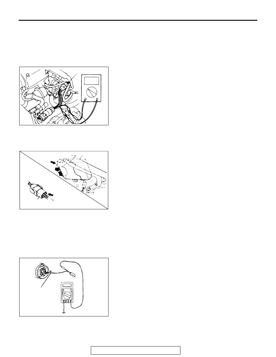
IF INSPECTING WITH THE CONNECTOR CONNECTED
<ORDINARY (NON-WATERPROOF) CONNECTORS>
Check by inserting the multi-meter test probe from the harness
side. Note that if the connector (control unit, etc.) is too small to
permit insertion of the test probe, it should not be forced; use
the backprobing tool for this purpose.
.
IF INSPECTING WITH THE CONNECTOR DISCONNECTED
<WHEN INSPECTING A FEMALE PIN>
From front side of the connector
Required Special Tool:
• MB991219: Inspection Harness (Included in MB991223,
Harness Set)
The inspection harness for connector pin contact pressure
should be used. The test probe should never be forcibly
inserted, as it may cause a defective contact.
ACX00863AE
SPECIAL TOOL
AC001606AB
CONNECTOR
ACX00865 AB
MB991219