Mitsubishi Montero (2004+). Manual - part 961


  Index      Mitsubishi     Mitsubishi Montero - service repair manual 2004 year


Search            


Content   ..  959  960  961  962   ..


Mitsubishi Montero (2004+). Manual - part 961


TRANSFER DIAGNOSIS <ACTIVE TRAC AWD II>

TSB Revision

AUTOMATIC TRANSMISSION

23A-419

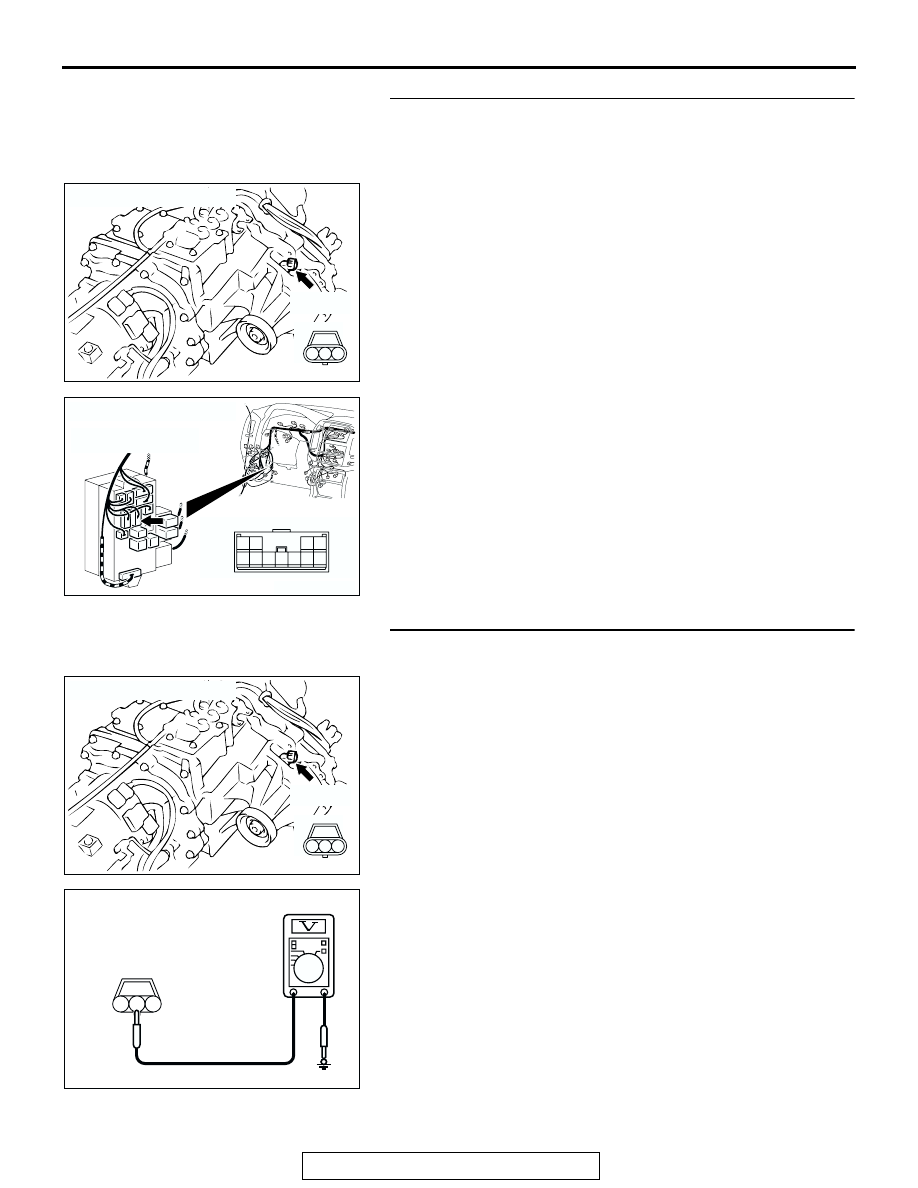
STEP 4. Check the harness for open circuit or short circuit 
to ground between front propeller shaft speed sensor 
connector C-13 terminal 3 and junction block connector 
D-212 terminal 9.
Q: Is the harness wire in good condition?

YES : Go to Step 5.
NO :  Repair or replace the harness wire.

STEP 5. Measure the sensor output voltage at front 
propeller shaft speed sensor connector C-13.
(1) Disconnect connector C-13 and measure at the harness 

side.

(2) Turn the ignition switch to the "ON" position.

(3) Measure the voltage between terminal 2 and ground.

• The voltage should measure between 4.5 and 4.9 volts.

(4) Turn the ignition switch to the "LOCK" (OFF) position.
Q: Is the measured voltage between 4.5 and 4.9 volts?

YES : Go to Step 11.
NO :  Go to Step 6.

AC204752

CONNECTOR : C-13

AB

2 3

1

C-13 (B)

AC204173

CONNECTOR : D-212

AZ

3

10

9

4

11

8

7

1

5

2

6

JUNCTION BLOCK
(FRONT VIEW)

AC204752

CONNECTOR : C-13

AB

2 3

1

C-13 (B)

AC204918 AU

C-13 HARNESS CONNECTOR : 
COMPONENT SIDE

3

1

2

TRANSFER DIAGNOSIS <ACTIVE TRAC AWD II>

TSB Revision

AUTOMATIC TRANSMISSION

23A-420

STEP 6. Measure the sensor output voltage at 
transfer-ECU connector E-109 by backprobing.
(1) Do not disconnect connector E-109.
(2) Disconnect connector C-13 at the front propeller shaft 

speed sensor.

(3) Turn the ignition switch to the "ON" position.

(4) Measure the voltage between terminal 7 and ground by 

backprobing.

• The voltage should measure between 4.5 and 4.9 volts.

(5) Turn the ignition switch to the "LOCK" (OFF) position.
Q: Is the measured voltage between 4.5 and 4.9 volts?

YES : Go to Step 7.
NO :  Go to Step 9.

STEP 7. Check front propeller shaft speed sensor 
connector C-13 and transfer-ECU connector E-109 for 
loose, corroded or damaged terminals, or terminals 
pushed back in the connector.
Q: Are the connectors and terminals in good condition?

YES : Go to Step 8.
NO :  Repair or replace the damaged components. Refer to 

GROUP 00E, Harness Connector Inspection 

P.00E-2

.

AC204176

CONNECTOR : E-109

BB

11 12

25

24

13

26

9

22

7

6

20

19

8

21

10

23

5

4

17

2

1

15

14

3

16

18

AC204918

11 12

25

24

13

26

9

22

7

6

20

19

8

21

10

23

5

4

17

2

1

15

14

3

16

18

CD

E-109 HARNESS CONNECTOR : 
HARNESS SIDE

AC204752

CONNECTOR : C-13

AB

2 3

1

C-13 (B)

AC204176

CONNECTOR : E-109

BB

11 12

25

24

13

26

9

22

7

6

20

19

8

21

10

23

5

4

17

2

1

15

14

3

16

18

TRANSFER DIAGNOSIS <ACTIVE TRAC AWD II>

TSB Revision

AUTOMATIC TRANSMISSION

23A-421

STEP 8. Check harness for open circuit or damage 
between front propeller shaft speed sensor connector C-13 
terminal 2 and transfer-ECU connector E-109 terminal 7.
Q: Is the harness wire in good condition?

YES : Go to Step 19.
NO :  Repair or replace the harness wire.

STEP 9. Check front propeller shaft speed sensor 
connector C-13 and transfer-ECU connector E-109 for 
loose, corroded or damaged terminals, or terminals 
pushed back in the connector.
Q: Are the connectors and terminals in good condition?

YES : Go to Step 10.
NO :  Repair or replace the damages components. Refer to 

GROUP 00E, Harness Connector Inspection 

P.00E-2

.

AC204752

CONNECTOR : C-13

AB

2 3

1

C-13 (B)

AC204176

CONNECTOR : E-109

BB

11 12

25

24

13

26

9

22

7

6

20

19

8

21

10

23

5

4

17

2

1

15

14

3

16

18

AC204752

CONNECTOR : C-13

AB

2 3

1

C-13 (B)

AC204176

CONNECTOR : E-109

BB

11 12

25

24

13

26

9

22

7

6

20

19

8

21

10

23

5

4

17

2

1

15

14

3

16

18

TRANSFER DIAGNOSIS <ACTIVE TRAC AWD II>

TSB Revision

AUTOMATIC TRANSMISSION

23A-422

STEP 10. Check harness for short circuit to ground 
between front propeller shaft speed sensor connector C-13 
terminal 2 and transfer-ECU connector E-109 terminal 7.
Q: Is the harness wire in good condition?

YES : Go to Step 11.
NO :  Repair or replace the harness wire.

STEP 11. Measure the ground circuit for resistance at the 
front propeller shaft speed sensor connector C-13.
(1) Disconnect connector C-13 and measure at the harness 

side.

(2) Measure the resistance between terminal 1 and ground.

• The resistance should measure less than 2 ohms.

Q: Is the measured resistance less than 2 ohms?

YES : Go to Step 16.
NO :  Go to Step 12.

AC204752

CONNECTOR : C-13

AB

2 3

1

C-13 (B)

AC204176

CONNECTOR : E-109

BB

11 12

25

24

13

26

9

22

7

6

20

19

8

21

10

23

5

4

17

2

1

15

14

3

16

18

AC204752

CONNECTOR : C-13

AB

2 3

1

C-13 (B)

AC204918

C-13 HARNESS CONNECTOR :
COMPONENT SIDE

DD

3

1

2


Content   ..  959  960  961  962   ..