Mitsubishi Montero (2004+). Manual - part 948


  Index      Mitsubishi     Mitsubishi Montero - service repair manual 2004 year


Search            


Content   ..  946  947  948  949   ..


Mitsubishi Montero (2004+). Manual - part 948


AUTOMATIC TRANSMISSION DIAGNOSIS

TSB Revision

AUTOMATIC TRANSMISSION

23A-367

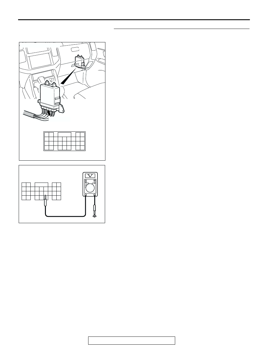
STEP 17. Measure the switch output voltage at PCM 
connector D-134.
(1) Disconnect connector D-134 and measure at the harness 

side.

(2) Turn the ignition switch to the "ON" position.

(3) Measure the voltage between terminal 77 and ground.

• The voltage should measure battery positive voltage 

when the selector lever is upshift and hold.

(4) Turn the ignition switch to the "LOCK" (OFF) position.
Q: Is the measured voltage battery positive voltage?

YES : Go to Step 14.
NO :  Go to Step 18.

AC204681AC

CONNECTOR: D-134

D-134 (GR)

61 62

63 64

65 66 67 68 69 70 71 72 73

82

89

81

88

80

79

78

77

87

86

85

76

75

74

84

83

AC204918 BN

D-134 HARNESS CONNECTOR : 
HARNESS SIDE

80

87

73

66

67

65

74

81

75

82

62 61

72

68

69

70

71

78

85

77

84 83

76

79

86

63

64

89 88

AUTOMATIC TRANSMISSION DIAGNOSIS

TSB Revision

AUTOMATIC TRANSMISSION

23A-368

STEP 18. Check PCM connector D-134 and intermediate 
connector E-114 for loose, corroded or damaged 
terminals, or terminals pushed back in the connector.
Q: Are the connectors and terminals in good condition?

YES : Go to Step 19.
NO :  Repair or replace the damaged components. Refer to 

GROUP 00E, Harness Connector Inspection 

P.00E-2

.

AC204681AC

CONNECTOR: D-134

D-134 (GR)

61 62

63 64

65 66 67 68 69 70 71 72 73

82

89

81

88

80

79

78

77

87

86

85

76

75

74

84

83

AC204176

CONNECTOR : E-114

BD

38

28

16

33

22

10

31

19

7

1

18

30

29

17

5

6

21

20

32

8

2

9

25

13

3

24

23

3435

1112

27

26

3637

14

4

15

AUTOMATIC TRANSMISSION DIAGNOSIS

TSB Revision

AUTOMATIC TRANSMISSION

23A-369

STEP 19. Check harness for open circuit or short circuit to 
ground between PCM connector D-134 terminal 77 and 
shift switch assembly connector E-115 terminal 7.
Q: Is the harness wire in good condition?

YES : Go to Step 25.
NO :  Repair or replace the harness wire.

STEP 20. Check the shift switch assembly.
Refer to 

P.23A-559

, Transmission Control.

Q: Is the switch operating properly?

YES : Go to Step 21.
NO :  Replace the shift switch assembly. Refer to 

P.23A-559

, Transmission Control.

AC204681AC

CONNECTOR: D-134

D-134 (GR)

61 62

63 64

65 66 67 68 69 70 71 72 73

82

89

81

88

80

79

78

77

87

86

85

76

75

74

84

83

AC204176

CONNECTOR : E-115

BE

8

3

4 5

1

2

6 7

AUTOMATIC TRANSMISSION DIAGNOSIS

TSB Revision

AUTOMATIC TRANSMISSION

23A-370

STEP 21. Check shift switch assembly connector E-115 for 
loose, corroded or damaged terminals, or terminals 
pushed back in the connector.
Q: Are the connector and terminals in good condition?

YES : Go to Step 22.
NO :  Repair or replace the damaged components. Refer to 

GROUP 00E, Harness Connector Inspection 

P.00E-2

.

STEP 22. Measure the switch output voltage at PCM 
connector D-134.
(1) Disconnect connector D-134 and measure at the harness 

side.

(2) Turn the ignition switch to the "ON" position.

(3) Measure the voltage between terminal 68 and ground.

• The voltage should measure battery positive voltage 

when the selector lever is downshift and hold.

(4) Turn the ignition switch to the "LOCK" (OFF) position.
Q: Is the measured voltage battery positive voltage?

YES : Go to Step 14.
NO :  Go to Step 23.

AC204176

CONNECTOR : E-115

BE

8

3

4 5

1

2

6 7

AC204681AC

CONNECTOR: D-134

D-134 (GR)

61 62

63 64

65 66 67 68 69 70 71 72 73

82

89

81

88

80

79

78

77

87

86

85

76

75

74

84

83

AC204918 BH

D-134 HARNESS CONNECTOR : 
HARNESS SIDE

80

87

73

66

67

65

74

81

75

82

62 61

72

68

69

70

71

78

85

77

84 83

76

79

86

63

64

89 88


Content   ..  946  947  948  949   ..