Mitsubishi Montero (2004+). Manual - part 932


  Index      Mitsubishi     Mitsubishi Montero - service repair manual 2004 year


Search            


Content   ..  930  931  932  933   ..


Mitsubishi Montero (2004+). Manual - part 932


AUTOMATIC TRANSMISSION DIAGNOSIS

TSB Revision

AUTOMATIC TRANSMISSION

23A-303

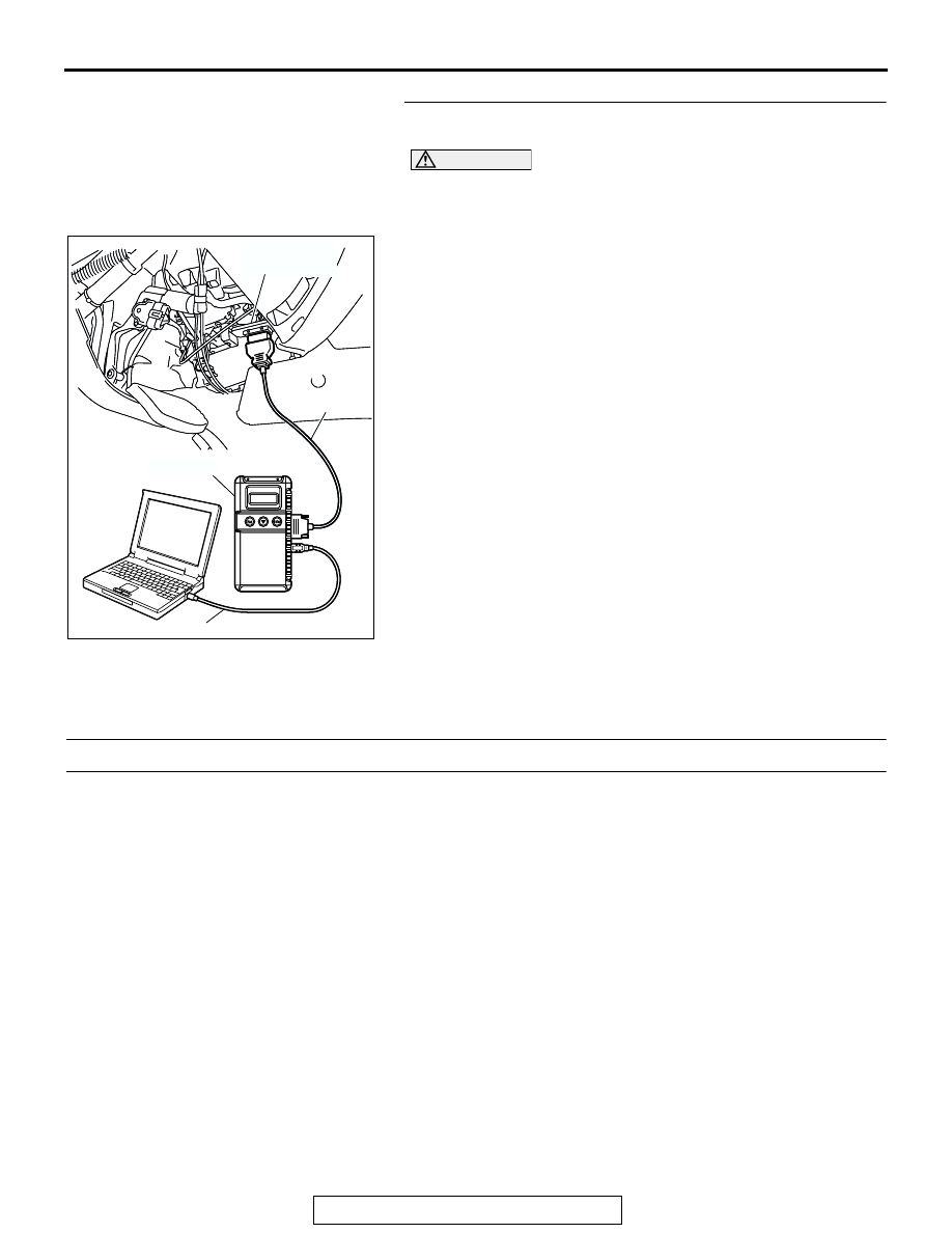
STEP 9. Using scan tool MB991958, read the A/T 
diagnostic trouble code.

CAUTION

To prevent damage to scan tool MB991958, always turn the 
ignition switch to the "LOCK" (OFF) position before con-
necting or disconnecting scan tool MB991958.
(1) Connect scan tool MB991958 to the data link connector.
(2) Turn the ignition switch to the "ON" position.
(3) Check for A/T diagnostic trouble code.
(4) Turn the ignition switch to the "LOCK" (OFF) position.
Q: Is DTC 56 set?

YES : Replace the PCM.
NO :  The procedure is complete.

SYMPTOM PROCEDURES <AUTOMATIC TRANSMISSION>

INSPECTION PROCEDURE 1: Engine does not Crank

.

COMMENT
If the engine does not crank when the selector lever 
is placed in the "P" or "N" position, the cause is prob-
ably a malfunction of transmission range switch sys-
tem, transmission control cable assembly, engine 
system, torque converter or transmission oil pump.

.

TROUBLESHOOTING HINTS (THE MOST LIKELY 
CAUSES FOR THIS CASE:)

• Malfunction of the transmission range switch

• Malfunction of the transmission control cable 

assembly

• Malfunction of the engine system

• Malfunction of the torque converter

• Malfunction of the transmission oil pump

• Malfunction of the PCM

DIAGNOSIS

Required Special Tool:

• MB991958: Scan Tool (MUT-III Sub Assembly)

• MB991824: V.C.I.

• MB991827: MUT-III USB Cable

• MB991911: MUT-III Main Harness B

AC307591 AC

MB991911

MB991824

MB991827

AC307591

DATA LINK

CONNECTOR

AUTOMATIC TRANSMISSION DIAGNOSIS

TSB Revision

AUTOMATIC TRANSMISSION

23A-304

STEP 1. Using scan tool MB991958, read the A/T 
diagnostic trouble code.

CAUTION

To prevent damage to scan tool MB991958, always turn the 
ignition switch to the "LOCK" (OFF) position before con-
necting or disconnecting scan tool MB991958.
(1) Connect scan tool MB991958 to the data link connector.
(2) Turn the ignition switch to the "ON" position.
(3) Check for A/T diagnostic trouble code.
(4) Turn the ignition switch to the "LOCK" (OFF) position.
Q: Is A/T DTCs 27 or 28 set?

YES <DTC 27 set> : Refer to 

P.23A-121

, DTC 27: 

Transmission Range Switch System (Open Circuit).

YES <DTC 28 set> : Refer to 

P.23A-150

, DTC 28: 

Transmission Range Switch System (Short Circuit).

NO :  Go to Step 2.

STEP 2. Check the transmission control cable assembly.
Move the selector lever to each position. The manual control 
lever position of the transmission range switch should match 
the transmission range.
Q: Is the manual control lever position correct?

YES : Go to Step 3.
NO :  Repair the transmission control cable. Refer to 

P.23A-546

Transmission Range Switch and Control 

Cable Adjustment. Retest the system to verify the 
repair.

STEP 3. Check the engine.
Refer to GROUP 13A, Diagnosis 

− Trouble Symptom Chart − 

Starting 

P.13A-30

.

Q: Is the inspection result good?

YES : Go to Step 4.
NO :  Repair or replace the appropriate engine 

components.

AC307591 AC

MB991911

MB991824

MB991827

AC307591

DATA LINK

CONNECTOR

ACX02178

P

R

N

D

3
2

L

AC

TRANSMISSION
RANGE SWITCH

MANUAL
CONTROL
LEVER

AUTOMATIC TRANSMISSION DIAGNOSIS

TSB Revision

AUTOMATIC TRANSMISSION

23A-305

STEP 4. Check the torque converter.
(1) Remove the transmission.
(2) Turn the torque converter and check for a binding or 

sticking condition. Check the ring gear for damaged or 
missing teeth.
NOTE: Since the torque converter drives the oil pump, turn-
ing the torque converter also checks for a binding oil pump. 
If either of these components are damaged the Transmis-
sion will need to be removed for inspection.

Q: Does the torque converter turn freely without any 

missing or damaged teeth?
YES : 
Go to Step 5.
NO :  Replace the torque converter.

STEP 5. Repair or replace the starter.
Q: Is the symptom eliminated?

YES : The procedure is complete.
NO :  Go to Step 6.

STEP 6. Replace the transmission oil pump.
Replace the transmission oil pump (Oil pump cannot be 
repaired). Refer to GROUP 23B, Transmission 

P.23B-14

. Con-

firm that the malfunction symptom is eliminated.
Q: Is the symptom eliminated?

YES : The procedure is complete.
NO :  Go to Step 7.

STEP 7. Replace the PCM.
Q: Does the engine crank when the selector lever is placed 

in the "P" or "N" position?
YES : 
The procedure is complete.
NO :  Start over at Step 1.

INSPECTION PROCEDURE 2: Does not Move Forward

.

COMMENT
If the engine is idling and the selector lever is shifted 
from "N" to "D" range and the vehicle does not drive 
forward then the cause is due to line pressure defect, 
under drive clutch or valve body malfunction.

.

TROUBLESHOOTING HINTS (THE MOST LIKELY 
CAUSES FOR THIS CASE:)

• Abnormal line pressure

• Malfunction of the underdrive solenoid valve

• Malfunction of the underdrive clutch

• Malfunction of the valve body

• Malfunction of the PCM

AC204883 AE

AC204883AI

AUTOMATIC TRANSMISSION DIAGNOSIS

TSB Revision

AUTOMATIC TRANSMISSION

23A-306

DIAGNOSIS

Required Special Tool:

• MB991958: Scan Tool (MUT-III Sub Assembly)

• MB991824: V.C.I.

• MB991827: MUT-III USB Cable

• MB991911: MUT-III Main Harness B

STEP 1. Using scan tool MB991958, check actuator test 
item 02: Underdrive Solenoid Valve.

CAUTION

To prevent damage to scan tool MB991958, always turn the 
ignition switch to the "LOCK" (OFF) position before con-
necting or disconnecting scan tool MB991958. 
(1) Connect scan tool MB991958 to the data link connector.
(2) Turn the ignition switch to the "ON" position.
(3) Set scan tool MB991958 to the actuator test mode.

• Item 02: Underdrive Solenoid Valve.

• An audible clicking or buzzing should be heard when 

the underdrive solenoid valve is energized.

(4) Turn the ignition switch to the "LOCK" (OFF) position.
Q: Is the solenoid valve operating properly?

YES : Go to Step 2.
NO :  Repair or replace the underdrive solenoid valve. 

Refer to GROUP 23B, Valve Body 

P.23B-63

. Then 

confirm that the symptom is eliminated.

STEP 2. Check the hydraulic pressure.
Shift the selector lever to the sport mode (1st gear) then mea-
sure the hydraulic pressure of each element in 1st speed to 
check and see if each respective hydraulic pressure is within 
the range of standard pressure. Refer to 

P.23A-26

, Hydraulic 

Pressure Test.
Q: Is the hydraulic pressure within the standard value?

YES : Go to Step 3.
NO :  Go to Step 4.

AC307591 AC

MB991911

MB991824

MB991827

AC307591

DATA LINK

CONNECTOR


Content   ..  930  931  932  933   ..