Mitsubishi Montero (2004+). Manual - part 916


  Index      Mitsubishi     Mitsubishi Montero - service repair manual 2004 year


Search            


Content   ..  914  915  916  917   ..


Mitsubishi Montero (2004+). Manual - part 916


AUTOMATIC TRANSMISSION DIAGNOSIS

TSB Revision

AUTOMATIC TRANSMISSION

23A-239

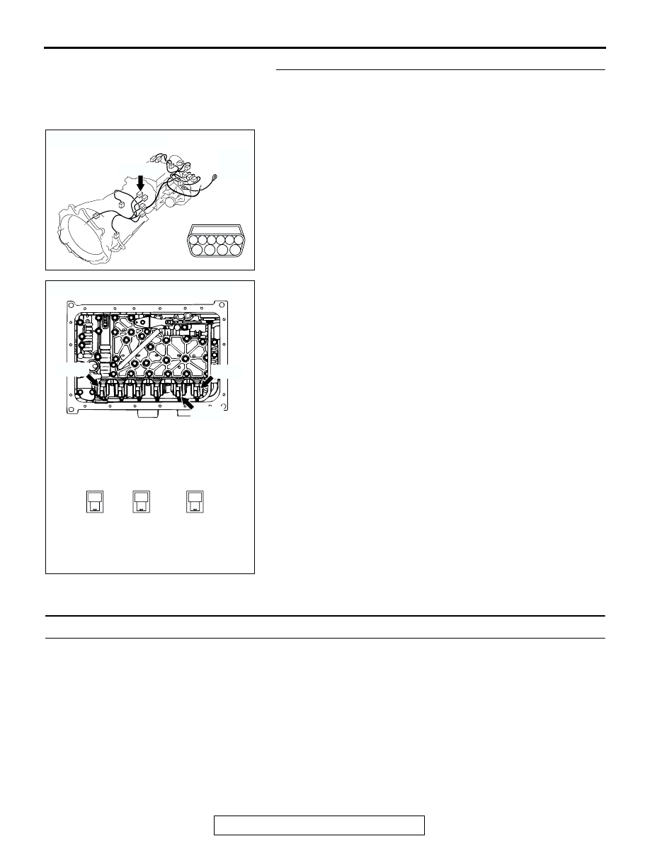
STEP 13. Check the harness for an open or short circuit to 
ground between A/T control solenoid valve assembly 
connector C-03 (terminals 6, 7, 8 and 10) and solenoid 
valve connectors C-03-4, C-03-5 and C-03-6.
Q: Is the harness wire in good condition?

YES : Replace the PCM.
NO :  Replace the harness wire.

DTC 36 (P0743): Torque Converter Clutch Solenoid Valve System

.

SOLENOID VALVE SYSTEM CIRCUIT
Refer to 

P.23A-177

.

.

CIRCUIT OPERATION
Refer to 

P.23A-177

.

.

DESCRIPTIONS OF MONITOR METHODS
If lock-up is not engaged, and solenoid terminal volt-
age is below specified value, PCM judges that torque 
converter clutch solenoid valve has a failure.

.

MONITOR EXECUTION
Continuous

.

MONITOR EXECUTION CONDITIONS (OTHER 
MONITOR AND SENSOR)

Other Monitor (There is no temporary DTC stored 

in memory for the item monitored below)

• DTC 41 (P0731): 1st gear incorrect ratio

• DTC 42 (P0732): 2nd gear incorrect ratio

• DTC 43 (P0733): 3rd gear incorrect ratio

AC204395

CONNECTOR : C-03

AE

C-03 (B)

6

10

4

9

5

3

8

2

7

1

AC204749

CONNECTORS : C-03-4, C-03-5, C-03-6

1
2

C-03-4

1
2

C-03-5

1
2

C-03-6

AD

C-03-4

C-03-6

C-03-5

AUTOMATIC TRANSMISSION DIAGNOSIS

TSB Revision

AUTOMATIC TRANSMISSION

23A-240

• DTC 44 (P0734): 4th gear incorrect ratio

• DTC 45 (P0735): 5th gear incorrect ratio

• DTC 46 (P0736): Reverse gear incorrect ratio

• DTC 31 (P0753): Low-reverse solenoid malfunc-

tion

• DTC 32 (P0758): Underdrive solenoid malfunc-

tion

• DTC 33 (P0763): Second solenoid malfunction

• DTC 34 (P0768): Overdrive solenoid malfunction

• DTC 35 (P0773): Reduction solenoid malfunction

• DTC 54 (P1751): A/T control relay malfunction

Sensor (The sensor below is determined to be 

normal)

• Low-reverse solenoid

• Underdrive solenoid

• Second solenoid

• Overdrive solenoid

• Reduction solenoid

• A/T control relay

.

LOGIC FLOW CHARTS (Monitor Sequence)

.

AC205240

START

END

TCC solenoid is in ON 
or OFF steady state

Voltage of battery > 10 V

Solenoid circuit 
voltage < 3 V

Continuous failure 
for 0.3 sec.

Good

Malfunction

Yes

No

Yes

No

Yes

No

Yes

No

TCC solenoid valve is in 
ON or OFF steady state

AC

AUTOMATIC TRANSMISSION DIAGNOSIS

TSB Revision

AUTOMATIC TRANSMISSION

23A-241

DTC SET CONDITIONS

Check Conditions

• Solenoid status: either solid ON or OFF.

• Voltage of battery: 10 volts or more.

Judgement Criteria

• Solenoid voltage: 3 volts or less. (0.3 second)

• If DTC 36 (P0743) is set consecutively four times, 

the transmission is locked into 3rd gear as a 
fail-safe measure, and the "N" range light flashes 
once per second.

.

OBD-II DRIVE CYCLE PATTERN
Start the engine, and keep the vehicle stopped in P 
range for 5 seconds.

.

TROUBLESHOOTING HINTS (THE MOST LIKELY 
CAUSES FOR THIS CODE TO BE SET ARE:)

• Malfunction of torque converter clutch solenoid 

valve

• Damaged harness, connector

• Malfunction of the PCM

DIAGNOSIS

Required Special Tool:

• MB991958: Scan Tool (MUT-III Sub Assembly)

• MB991824: V.C.I.

• MB991827: MUT-III USB Cable

• MB991911: MUT-III Main Harness B

STEP 1. Using scan tool MB991958, check actuator test 
item 06: Torque Converter Clutch Solenoid Valve.

CAUTION

To prevent damage to scan tool MB991958, always turn the 
ignition switch to the "LOCK" (OFF) position before con-
necting or disconnecting scan tool MB991958.
(1) Connect scan tool MB991958 to the data link connector.
(2) Turn the ignition switch to the "ON" position.
(3) Set scan tool MB991958 to the actuator test mode.

• Item 06: Torque Converter Clutch Solenoid Valve.

• An audible clicking or buzzing should be heard when 

the torque converter clutch solenoid valve is ener-
gized.

(4) Turn the ignition switch to the "LOCK" (OFF) position.
Q: Is the solenoid valve operating properly?

YES : It can be assumed that this malfunction is intermittent. 

Refer to GROUP 00, How to Use 
Troubleshooting/Inspection Service Points 

− How to 

Cope with Intermittent Malfunctions 

P.00-6

.

NO :  Go to Step 2.

AC307591 AC

MB991911

MB991824

MB991827

AC307591

DATA LINK

CONNECTOR

AUTOMATIC TRANSMISSION DIAGNOSIS

TSB Revision

AUTOMATIC TRANSMISSION

23A-242

STEP 2. Using scan tool MB991958, read the A/T 
diagnostic trouble code.
(1) Connect scan tool MB991958 to the data link connector.
(2) Turn the ignition switch to the "ON" position.
(3) Check for A/T diagnostic trouble code.
(4) Turn the ignition switch to the "LOCK" (OFF) position.
Q: Is DTC 54 set? (DTC 54 may be set along with multiple 

DTCs).
YES : 
Refer to 

P.23A-277

 DTC 54: A/T Control Relay 

System.

NO :  Go to Step 3.

STEP 3. Using scan tool MB991958, read the A/T 
diagnostic trouble code.
(1) Connect scan tool MB991958 to the data link connector.
(2) Turn the ignition switch to the "ON" position.
(3) Check for A/T diagnostic trouble code.
(4) Turn the ignition switch to the "LOCK" (OFF) position.
Q: Are DTC 31 and DTC 35 set? (Multiple DTCs may be set).

YES : Go to Step 8.
NO :  Go to Step 4.

AC307591 AC

MB991911

MB991824

MB991827

AC307591

DATA LINK

CONNECTOR

AC307591 AC

MB991911

MB991824

MB991827

AC307591

DATA LINK

CONNECTOR


Content   ..  914  915  916  917   ..