Mitsubishi Montero (2004+). Manual - part 883


  Index      Mitsubishi     Mitsubishi Montero - service repair manual 2004 year


Search            


Content   ..  881  882  883  884   ..


Mitsubishi Montero (2004+). Manual - part 883


AUTOMATIC TRANSMISSION DIAGNOSIS

TSB Revision

AUTOMATIC TRANSMISSION

23A-107

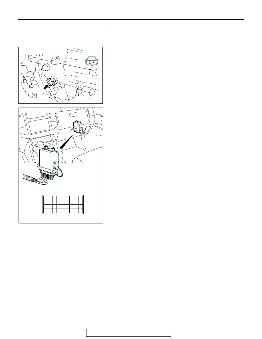
STEP 14. Check the harness for open circuit or damage 
between output shaft speed sensor connector C-02 
terminal 1 and PCM connector D-134 terminal 88.
Q: Is the harness wire in good condition?

YES : Go to Step 16.
NO :  Repair or replace the harness wire.

AC204746

CONNECTOR : C-02

C-02 (GR)

AB

1 2 3

AC204681AC

CONNECTOR: D-134

D-134 (GR)

61 62

63 64

65 66 67 68 69 70 71 72 73

82

89

81

88

80

79

78

77

87

86

85

76

75

74

84

83

AUTOMATIC TRANSMISSION DIAGNOSIS

TSB Revision

AUTOMATIC TRANSMISSION

23A-108

STEP 15. Check PCM connector D-134 for loose, corroded 
or damaged terminals, or terminals pushed back in the 
connector.
Q: Are the connector and terminals in good condition?

YES : Replace the PCM.
NO :  Repair or replace the damaged components. Refer to 

GROUP 00E, Harness Connector Inspection 

P.00E-2

.

AC204681AC

CONNECTOR: D-134

D-134 (GR)

61 62

63 64

65 66 67 68 69 70 71 72 73

82

89

81

88

80

79

78

77

87

86

85

76

75

74

84

83

AUTOMATIC TRANSMISSION DIAGNOSIS

TSB Revision

AUTOMATIC TRANSMISSION

23A-109

STEP 16. Using an oscilloscope, check the output shaft 
speed sensor waveform at PCM connector D-134 by 
backprobing.
(1) Do not disconnect connector D-134.

(2) Connect an oscilloscope probe to PCM connector D-134 

terminal 73 and terminal 88 by backprobing.

(3) Start the engine and drive the vehicle at constant speed of 

50 km/h (31 mph) (Gear range: 4th gear).

(4) Check the output shaft speed sensor waveform.

• The output shaft speed sensor waveform should show a 

pattern similar to the illustration. The maximum value 
should be 4.8 volts and more and the minimum value 
0.8 volt and less. The output waveform should not con-
tain electrical noise.

(5) Turn the ignition switch to the "LOCK" (OFF) position.
Q: Is the waveform normal?

YES : Go to Step 19.
NO :  Go to Step 17.

AC204681AC

CONNECTOR: D-134

D-134 (GR)

61 62

63 64

65 66 67 68 69 70 71 72 73

82

89

81

88

80

79

78

77

87

86

85

76

75

74

84

83

AC204946 AF

OSCILLO-
SCOPE

PROBE

D-134 HARNESS CONNECTOR : 
HARNESS SIDE

76

85

65

72

71

73

82

75

81

74

63 64

66

70

69

68

67

78

87

79

88 89

80

77

86

62

61

83 84

ACX02131

NORMAL WAVEFORM

AD

(V)

5

0

AUTOMATIC TRANSMISSION DIAGNOSIS

TSB Revision

AUTOMATIC TRANSMISSION

23A-110

STEP 17. Replace the output shaft speed sensor.
(1) Replace the output shaft speed sensor. Refer to GROUP 

23B, Transmission 

P.23B-14

.

(2) Test drive the vehicle.
(3) Check for A/T diagnostic trouble code.
Q: Is A/T DTC 23 set?

YES : Go to Step 18.
NO :  The procedure is complete.

STEP 18. Replace the direct planetary carrier.
(1) Replace the direct planetary carrier. Refer to GROUP 23B, 

Transmission 

P.23B-14

.

(2) Test drive the vehicle.
(3) Check for A/T diagnostic trouble code.
Q: Is A/T DTC 23 set?

YES : An A/T DTC may have set due to external radio 

frequency interference (RFI) possibility caused by 
cellular phone activity, or aftermarket components 
installed on the vehicle.

NO :  The procedure is complete.

STEP 19. Using scan tool MB991958, check data list item 
23: Output Shaft Speed Sensor.

CAUTION

To prevent damage to scan tool MB991958, always turn the 
ignition switch to the "LOCK" (OFF) position before con-
necting or disconnecting scan tool MB991958.
(1) Connect scan tool MB991958 to the data link connector.
(2) Start the engine.
(3) Set scan tool MB991958 to data reading mode.

• Item 23: Output Shaft Speed Sensor.

• When driving at constant speed of 50 km/h (31 

mph), the display should be "1,400 

− 1,700 r/min" 

(Gear range: 4th gear).

(4) Turn the ignition switch to the "LOCK" (OFF) position.
Q: Is the sensor operating properly?

YES : It can be assumed that this malfunction is intermittent. 

Refer to GROUP 00, How to Use 
Troubleshooting/Inspection Service Points 

− How to 

Cope with Intermittent Malfunction 

P.00-6

.

NO :  Replace the PCM.

ACX01223 AE

OUTPUT SHAFT
SPEED SENSOR

AC204883

DIRECT 
PLANETARY
CARRIER

AF

AC307591 AC

MB991911

MB991824

MB991827

AC307591

DATA LINK

CONNECTOR


Content   ..  881  882  883  884   ..