Mitsubishi Montero (2004+). Manual - part 816


  Index      Mitsubishi     Mitsubishi Montero - service repair manual 2004 year


Search            


Content   ..  814  815  816  817   ..


Mitsubishi Montero (2004+). Manual - part 816


INPUT SIGNAL PROCEDURES

TSB Revision

SIMPLIFIED WIRING SYSTEM (SWS)

54B-521

.

CIRCUIT OPERATION
The ETACS-ECU operates the following functions or 
systems according to signal from the driver's or front 
passenger's door switches:

• Ignition key reminder tone alarm function

• Light reminder tone alarm function

• Power window timer function

• Headlight automatic shutdown function

• Dome light

.

TECHNICAL DESCRIPTION (COMMENT)
If the signal is not normal, the functions or systems, 
which are described in "CIRCUIT OPERATION", do 
not work normally. If the signal is not normal, the 
driver's or front passenger's door switch or the 
ETACS-ECU may be defective.

.

TROUBLESHOOTING HINTS

• The driver's or front passenger's door switches 

may be defective

• The ETACS-ECU may be defective

• The wiring harness or connectors may have 

loose, corroded, or damaged terminals, or termi-
nals pushed back in the connector

DIAGNOSIS

Required Special Tools:

• MB991223: Harness Set

• MB991958: Scan Tool (MUT-III Sub Assembly)

• MB991824: Vehicle Communication Interface (V.C.I.)

• MB991827: MUT-III USB Cable

• MB991911: MUT-III Main Harness B
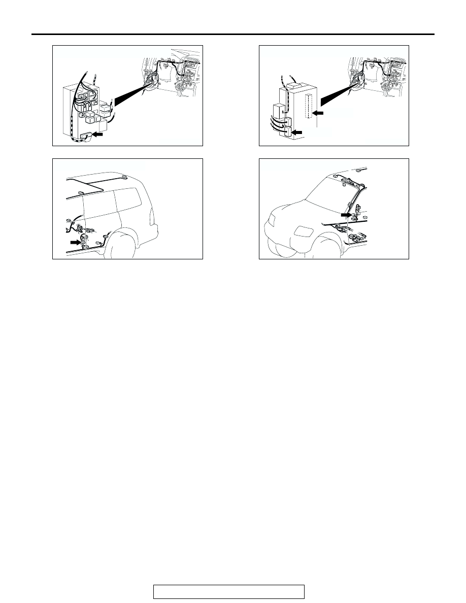
AC204173

CONNECTOR : D-217               

AM

AC204174

CONNECTORS : D-222, D-224

D-224(B)

AH

D-222

AC204178

CONNECTOR : F-14

AL

AC204177

CONNECTOR : F-22

AM

INPUT SIGNAL PROCEDURES

TSB Revision

SIMPLIFIED WIRING SYSTEM (SWS)

54B-522

STEP 1. Check the input signal by using the pulse check 
mode of the monitor.
Check the input signals from the front door switches.

CAUTION

To prevent damage to scan tool MB991958, always turn the 
ignition switch to the "LOCK" (OFF) position before con-
necting or disconnecting scan tool MB991958.
(1) Connect scan tool MB991502 to the data link connector 

(16-pin).

(2) Operate scan tool MB991958 according to the procedure 

below to display "PULSE CHECK."

1. Select "SYSTEM SELECT."
2. Select "SWS."
3. Select "PULSE CHECK."

(3) When each front door is opened and closed, check if scan 

tool MB991958 sounds or not.

Q: Does scan tool MB991958 sound when each front door 

is opened and closed?
When the driver's door is opened and closed, scan tool 
MB991958 does not sound. : 
Go to Step 2.
When the front passenger's door is opened and closed, 
scan tool MB991958 does not sound. : 
Go to Step 7.
when each front door is opened and closed, scan tool 
MB991958 sounds.  : 
Replace the ETACS-ECU. If the 

functions, which are described in "CIRCUIT 
OPERATION", work normally, the input signal from 
the driver's or the front passenger's door switch 
should be normal.

STEP 2. Check driver's door switch connector F-14 for 
loose, corroded or damaged terminals, or terminals 
pushed back in the connector. 
Q: Is driver's door switch connector F-14 in good 

condition?
YES : 
Go to Step 3.
NO :  Repair or replace the damaged component(s). Refer 

to GROUP 00E, Harness Connector Inspection 

P.00E-2

. If the functions, which are described in 

"CIRCUIT OPERATION", work normally, the input 
signal from the driver's door switch should be normal.

AC307591 AB

MB991911

DATA LINK

CONNECTOR

MB991824

MB991827

AC204178

CONNECTOR : F-14

AF

HARNESS SIDE

1

2

3

F-14

INPUT SIGNAL PROCEDURES

TSB Revision

SIMPLIFIED WIRING SYSTEM (SWS)

54B-523

STEP 3. Check the driver's door switch.
Remove the driver's door switch. Then check the continuity 
between the switch terminals and the switch body.

Q: Is the driver's door switch in good condition?

YES : Go to Step 4.
NO :  Replace the driver's door switch. If the functions, 

which are described in "CIRCUIT OPERATION", work 
normally, the input signal from the driver's door switch 
should be normal.

STEP 4. Measure at the lower metal part of the driver's 
door switch in order to check the ground circuit to the 
driver's door switch.
NOTE: Check that the driver's door switch is grounded to the 
vehicle body by means of its mounting screw.
Remove the cap, and measure the resistance value between 
the lower metal part and the ground. 

• The resistance should equal 2 ohms or less.

Q: Is the measured resistance 2 ohms or less?

YES : Go to Step 5.
NO :  Check the fit of the switch, and repair if necessary. If 

the functions, which are described in "CIRCUIT 
OPERATION", work normally, the input signal from 
the driver's door switch should be normal.

STEP 5. Check ETACS-ECU connector D-222 for loose, 
corroded or damaged terminals, or terminals pushed back 
in the connector. 
Q: Is ETACS-ECU connector D-222 in good condition?

YES : Go to Step 6.
NO :  Repair or replace the damaged component(s). Refer 

to GROUP 00E, Harness Connector Inspection 

P.00E-2

. If the functions, which are described in 

"CIRCUIT OPERATION", work normally, the input 
signal from the driver's door switch should be normal.

SWITCH 
POSITION

TESTER 
CONNECTION

SPECIFIED 
CONDITION

Released (ON)

− switch body

Less than 2 ohms

Depressed (OFF) 1 

− switch body

Open circuit

1 2 3

ACX01865 AC

ON

OFF

ACX01600AB

METAL PART

CUP

AC204174

CONNECTOR : D-222

AB

1

2

3

5

6

4

9 8

121110

13

15 14

16

17

7

19

20

18

JUNCTION BLOCK SIDE

D-222

INPUT SIGNAL PROCEDURES

TSB Revision

SIMPLIFIED WIRING SYSTEM (SWS)

54B-524

STEP 6. Check the wiring harness between driver's door 
switch connector F-14 (terminal 1) and ETACS-ECU 
connector D-222 (terminal 9).

NOTE: Also check intermediate connector D-125 and junction 
block connector D-217 for loose, corroded, or damaged termi-
nals, or terminals pushed back in the connector. If junction 
block connector D-217 or intermediate connector D-125 is 
damaged, Repair or replace the damaged component(s) as 
described in GROUP 00E, Harness Connector Inspection 

P.00E-2

.

Q: Is the wiring harness between driver's door switch 

connector F-14 and ETACS-ECU connector D-222 in 
good condition?
YES : 
Replace the ETACS-ECU. If the functions, which are 

described in "CIRCUIT OPERATION", work normally, 
the input signal from the driver's door switch should 
be normal.

NO :  The wiring harness may be damaged or the 

connector(s) may have loose, corroded or damaged 
terminals, or terminals pushed back in the connector. 
Repair the wiring harness as necessary. If the 
functions, which are described in "CIRCUIT 
OPERATION", work normally, the input signal from 
the driver's door switch should be normal.

AC204174

CONNECTOR : D-222

AB

1

2

3

5

6

4

9 8

121110

13

15 14

16

17

7

19

20

18

JUNCTION BLOCK SIDE

D-222

AC204178

CONNECTOR : F-14

AF

HARNESS SIDE

1

2

3

F-14

AC204170

CONNECTOR : D-125

AO

9

8

6 7

5

3 4

20

32

21

33

43

17 18

30

41

16

29

28

39 40

13

25

12

24

35 36

14

26

37

15

27

38

19

31

42

1

10

22

2

11

23

34

AC204173

CONNECTOR : D-217

AG

HARNESS SIDE

8

1

11 10

3

4

12

9

2

13

14

6 5

15

7

D-217


Content   ..  814  815  816  817   ..