Mitsubishi Montero (2004+). Manual - part 770


  Index      Mitsubishi     Mitsubishi Montero - service repair manual 2004 year


Search            


Content   ..  768  769  770  771   ..


Mitsubishi Montero (2004+). Manual - part 770


SYMPTOM PROCEDURES

TSB Revision

SIMPLIFIED WIRING SYSTEM (SWS)

54B-337

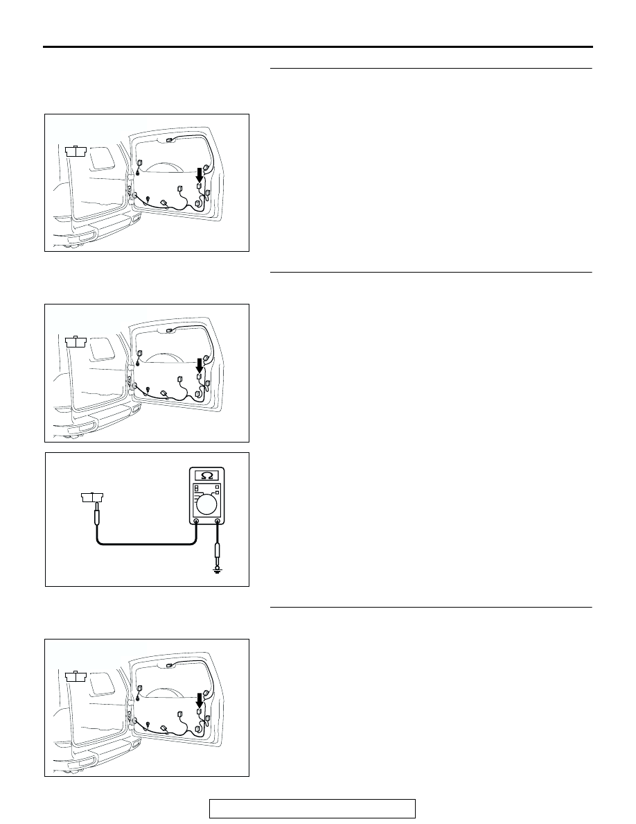
STEP 39. Check license plate light assembly connector 
I-04 for loose, corroded or damaged terminals, or terminals 
pushed back in the connector.
Q: Is license plate light assembly connector I-04 in good 

condition?
YES : 
Go to Step 40.
NO :  Repair or replace the damaged component(s). Refer 

to GROUP 00E, Harness Connector Inspection 

P.00E-2

. Verify that the license plate lights illuminate 

normally.

STEP 40. Check the ground circuit to the license plate 
light. Test at license plate light assembly connector I-04. 
(1) Disconnect license plate light assembly connector I-04 and 

measure the resistance available at the wiring harness side 
of the connector.

(2) Measure the resistance value between terminal 1 and 

ground.

• The resistance should equal 2 ohms or less.

Q: Is the measured resistance 2 ohms or less?

YES : Go to Step 42.
NO :  Go to Step 41.

STEP 41. Check the wiring harness between license plate 
light assembly connector I-04 (terminal 1) and ground.
Q: Is the wiring harness between license plate light 

assembly connector I-04 (terminal 1) and ground in 
good condition?
YES : 
No action is necessary and testing is complete.
NO :  The wiring harness may be damaged or the 

connector(s) may have loose, corroded or damaged 
terminals, or terminals pushed back in the connector. 
Repair the wiring harness as necessary. Verify that 
the license plate lights illuminate normally.

AC204182

CONNECTOR : I-04

AB

HARNESS SIDE

1

2

AC204182

CONNECTOR : I-04

AB

HARNESS SIDE

1

2

AC100262

1

2

AB

CONNECTOR I-04
(HARNESS SIDE)

AC204182

CONNECTOR : I-04

AB

HARNESS SIDE

1

2

SYMPTOM PROCEDURES

TSB Revision

SIMPLIFIED WIRING SYSTEM (SWS)

54B-338

STEP 42. Check front-ECU connector A-07X for loose, 
corroded or damaged terminals, or terminals pushed back 
in the connector.
Q: Is front-ECU connector A-07X in good condition?

YES : Go to Step 43.
NO :  Repair or replace the damaged component(s). Refer 

to GROUP 00E, Harness Connector Inspection 

P.00E-2

. Verify that the license plate lights illuminate 

normally.

STEP 43. Check the wiring harness between license plate 
light assembly connector I-04 (terminal 2) and front-ECU 
connector A-07X (terminal 8).

AC204183

CONNECTOR : A-07X

AB

2 1

3

4

6

7

8

9

5

11 10

RELAY BOX SIDE

AC204183

CONNECTOR : A-07X

AB

2 1

3

4

6

7

8

9

5

11 10

RELAY BOX SIDE

AC204182

CONNECTOR : I-04

AB

HARNESS SIDE

1

2

SYMPTOM PROCEDURES

TSB Revision

SIMPLIFIED WIRING SYSTEM (SWS)

54B-339

NOTE: Also check intermediate connectors D-28, D-111 and 
G-10 for loose, corroded, or damaged terminals, or terminals 
pushed back in the connector. If intermediate connector D-28, 
D-111 or G-10 is damaged, repair or replace the damaged com-
ponent(s) as described in GROUP 00E, Harness Connector 
Inspection 

P.00E-2

.

Q: Is the wiring harness between license plate light 

assembly connector I-04 (terminal 2) and front-ECU 
connector A-07X (terminal 8) in good condition?
YES : 
No action is necessary and testing is complete.
NO :  The wiring harness may be damaged or the 

connector(s) may have loose, corroded or damaged 
terminals, or terminals pushed back in the connector. 
Repair the wiring harness as necessary. Verify that 
the license plate lights illuminate normally.

STEP 44. Check the side marker light bulb (LH).
(1) Remove the side marker light bulb (LH).
(2) Verify that the side marker light bulb (LH) is not damaged or 

burned out.

Q: Is the side marker light bulb (LH) in good condition?

YES : Go to Step 45.
NO :  Replace the side marker light bulb (LH). Verify that 

the side marker lights (LH) illuminates normally.

AC204170

CONNECTOR : D-28

AI

2 3

27

32

28

33

16

15

4 5

19

18

29

17

34

7 8

35

22

21

9 10

30

36

31

37

25

24

23

6

20

1

14

26

11

13

12

38

AC204171

CONNECTOR : D-111

BH

9

8

6 7

5

3 4

20

32

21

33

43

17 18

30

41

16

29

28

39 40

13

25

12

24

35 36

14

26

37

15

27

38

19

31

42

1

10

22

2

11

23

34

AC204179

CONNECTOR : G-10

AD

4

10

8

7

3

9

5

1

6

2

SYMPTOM PROCEDURES

TSB Revision

SIMPLIFIED WIRING SYSTEM (SWS)

54B-340

STEP 45. Check side marker light (LH) connector G-02 for 
loose, corroded or damaged terminals, or terminals 
pushed back in the connector.
Q: Is side marker light (LH) connector G-02 in good 

condition?
YES : 
Go to Step 46.
NO :  Repair or replace the damaged component(s). Refer 

to GROUP 00E, Harness Connector Inspection 

P.00E-2

. Verify that the side marker lights (LH) 

illuminates normally.

STEP 46. Check the ground circuit to the side marker light 
(LH). Test at side marker light (LH) connector G-02. 
(1) Disconnect side marker light (LH) connector G-02 and 

measure the resistance available at the wiring harness side 
of the connector.

(2) Measure the resistance value between terminal 4 and 

ground.

• The resistance should equal 2 ohms or less.

Q: Is the measured resistance 2 ohms or less?

YES : Go to Step 48.
NO :  Go to Step 47.

STEP 47. Check the wiring harness between side marker 
light (LH) connector G-02 (terminal 4) and ground.
Q: Is the wiring harness between side marker light (LH) 

connector G-02 (terminal 4) and ground in good 
condition?
YES : 
Replace the side marker light socket. Verify that the 

side marker light (LH) illuminates normally.

NO :  The wiring harness may be damaged or the 

connector(s) may have loose, corroded or damaged 
terminals, or terminals pushed back in the connector. 
Repair the wiring harness as necessary. Verify that 
the side marker light (LH) illuminates normally.

AC204179

CONNECTOR : G-02

AB

HARNESS SIDE

G-02(B)

G-02(B)

1

4

2

3

5

6

AC204179

CONNECTOR : G-02

AB

HARNESS SIDE

G-02(B)

G-02(B)

1

4

2

3

5

6

AC100256

1

4

2

3

5

6

AB

CONNECTOR G-02
(HARNESS SIDE)

AC204179

CONNECTOR : G-02

AB

HARNESS SIDE

G-02(B)

G-02(B)

1

4

2

3

5

6


Content   ..  768  769  770  771   ..