Mitsubishi Montero (2004+). Manual - part 768
SYMPTOM PROCEDURES
TSB Revision
SIMPLIFIED WIRING SYSTEM (SWS)
54B-329
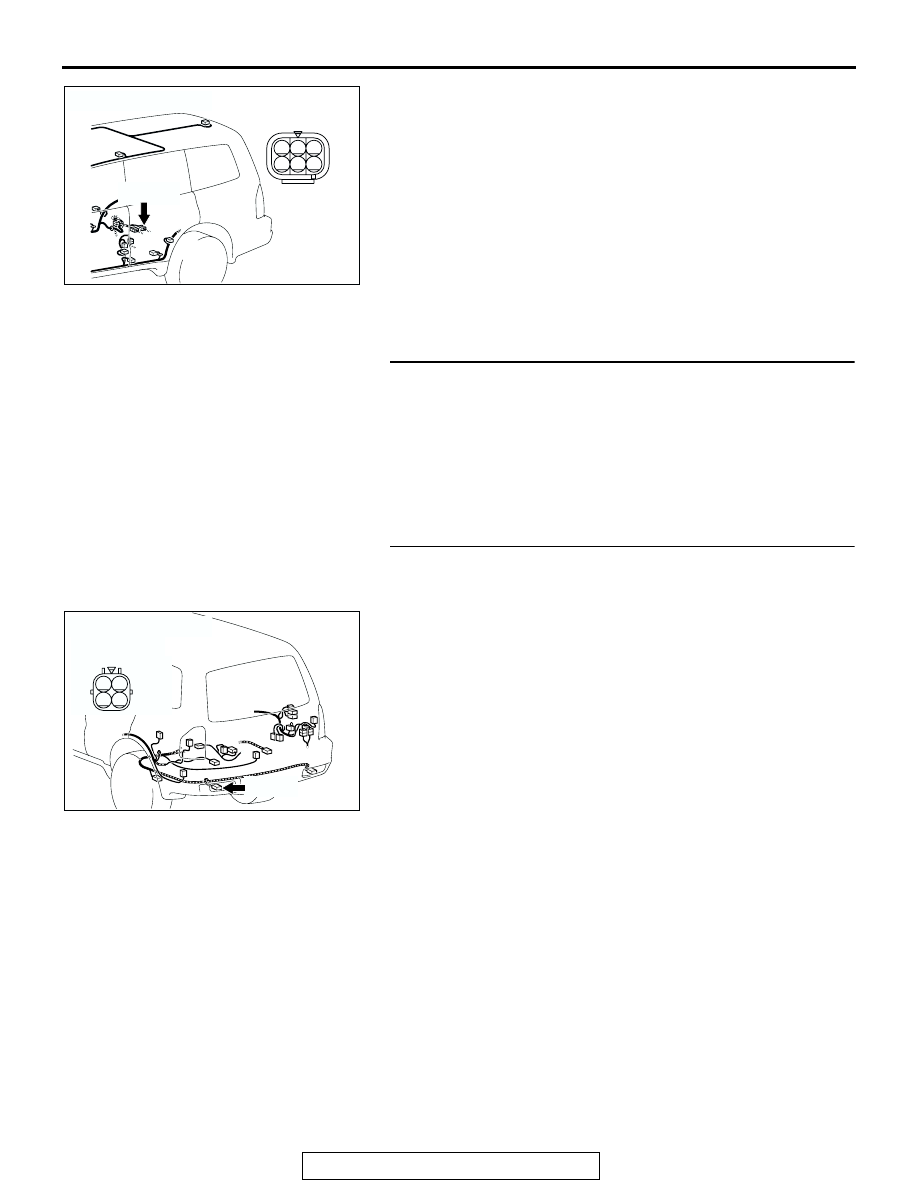
NOTE: Also check intermediate connector F-10 for loose, cor-
roded, or damaged terminals, or terminals pushed back in the
connector. If intermediate connector F-10 is damaged, repair or
replace the damaged component(s) as described in GROUP
00E, Harness Connector Inspection
Q: Is the wiring harness between rear light (LH) connector
G-16 (terminal 3) and ground in good condition?
YES : No action is necessary and testing is complete.
NO : The wiring harness may be damaged or the
connector(s) may have loose, corroded or damaged
terminals, or terminals pushed back in the connector.
Repair the wiring harness as necessary. Verify that
the taillights illuminate normally.
STEP 26. Check the taillight bulb (LH).
(1) Remove the taillight bulb (LH).
(2) Verify that the taillight bulb (LH) is not damaged or burned
out.
Q: Is the taillight bulb (LH) in good condition?
YES : Go to Step 27.
NO : Replace the taillight bulb (LH). Verify that the taillights
(LH) illuminates normally.
STEP 27. Check rear light (LH) connector G-16 for loose,
corroded or damaged terminals, or terminals pushed back
in the connector.
Q: Is rear light (LH) connector G-16 in good condition?
YES : Go to Step 28.
NO : Repair or replace the damaged component(s). Refer
to GROUP 00E, Harness Connector Inspection
. Verify that the taillights (LH) illuminates
normally.
AC204178
CONNECTOR : F-10
AD
F-10(GR)
F-10(GR)
3
1
2
4
5
6
AC204179
CONNECTOR : G-16
AH
HARNESS SIDE
G-16(B)
G-16(B)
3
4
2
1