Mitsubishi Montero (2004+). Manual - part 758


  Index      Mitsubishi     Mitsubishi Montero - service repair manual 2004 year


Search            


Content   ..  756  757  758  759   ..


Mitsubishi Montero (2004+). Manual - part 758


SYMPTOM PROCEDURES

TSB Revision

SIMPLIFIED WIRING SYSTEM (SWS)

54B-289

STEP 3. Check the input signal (by using the pulse check 
mode of the monitor.)
Check input signal from the driver's side seat belt switch.
Operate scan tool MB991958 according to the procedure below 
to display "PULSE CHECK."

1. Select "SYSTEM SELECT."
2. Select "SWS."
3. Select "PULSE CHECK."

• When the driver's seat belt is fastened, check if scan tool 

MB991958 sounds or not.

Q: Does scan tool MB991958 sound when the driver's side 

seat belt is fastened?
YES : 
Go to Step 4.
NO :  Refer to Inspection Procedure P-3 "ETACS-ECU does 

not receive any signal from the driver's side seat belt 
switch 

P.54B-553

."

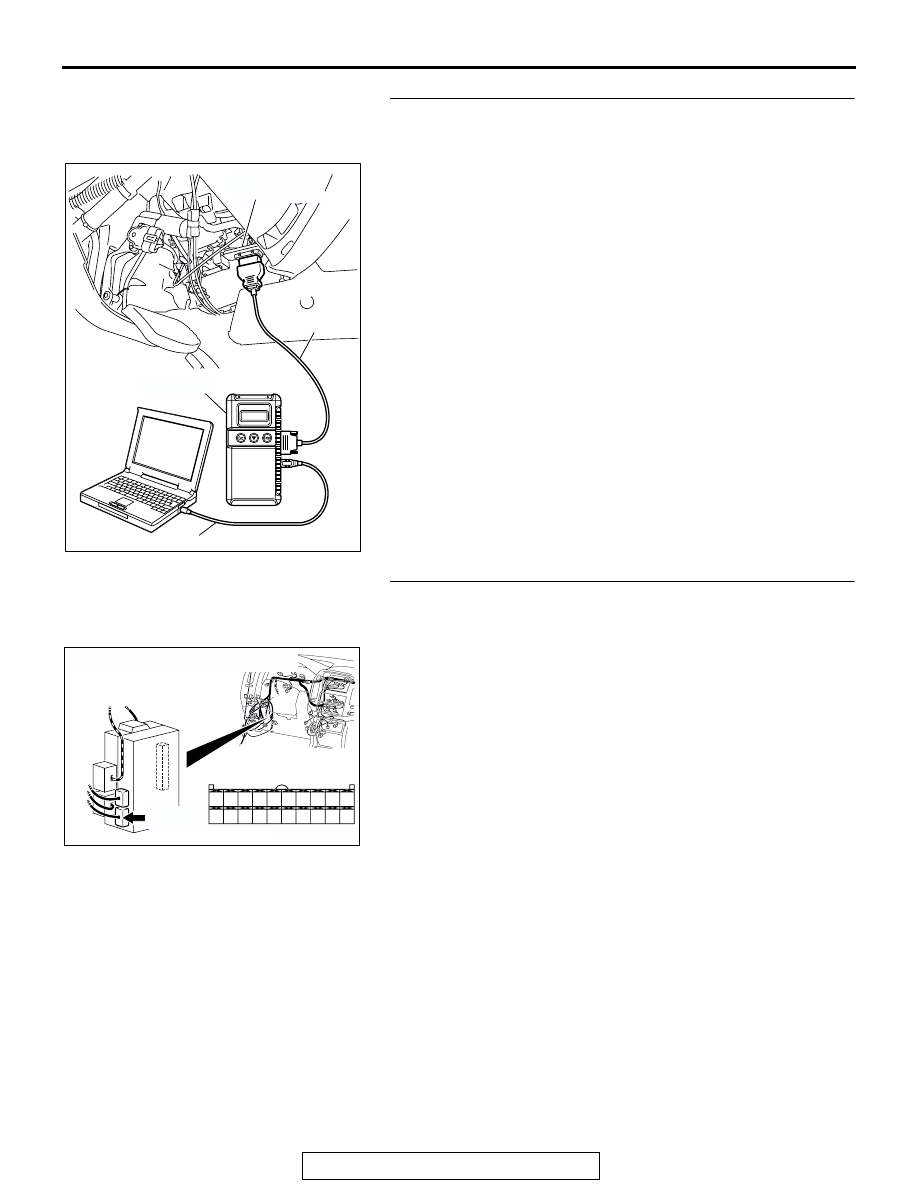
STEP 4. Check ETACS-ECU connector D-224 for loose, 
corroded or damaged terminals, or terminals pushed back 
in the connector.
Q: Is ETACS-ECU connector D-224 in good condition?

YES : Go to Step 5.
NO :  Repair or replace the damaged component(s). Refer 

to GROUP 00E, Harness Connector Inspection 

P.00E-2

. Verify that the seat belt warning light 

illuminates normally.

AC307591 AB

MB991911

DATA LINK

CONNECTOR

MB991824

MB991827

AC204174

CONNECTOR : D-224

AD

D-224(B)

D-224(B)

HARNESS SIDE

21

23

24

22

32

3433

31

26

27

28

3029

38

39

40

36

37

25

35

SYMPTOM PROCEDURES

TSB Revision

SIMPLIFIED WIRING SYSTEM (SWS)

54B-290

STEP 5. Check at ETACS-ECU connector D-224 in order to 
check the ground circuit to the seat belt warning light.
(1) Disconnect ETACS-ECU connector D-224, and measure at 

the wiring harness side. 

(2) Turn the ignition switch to the "ON" position.

(3) Connect terminal 39 to ground.
Q: Does the seat belt warning light illuminate?

YES : Replace the ETACS-ECU. Verify that the seat belt 

warning light illuminates normally.

NO :  Go to Step 6.

STEP 6. Check combination meter connector D-03 and 
D-04 for loose, corroded or damaged terminals, or 
terminals pushed back in the connector.
Q: Are combination meter connector D-03 and D-04 in 

good condition?
YES : 
Go to Step 7.
NO :  Repair or replace the damaged component(s). Refer 

to GROUP 00E, Harness Connector Inspection 

P.00E-2

. Verify that the seat belt warning light 

illuminates normally.

AC204174

CONNECTOR : D-224

AD

D-224(B)

D-224(B)

HARNESS SIDE

21

23

24

22

32

3433

31

26

27

28

3029

38

39

40

36

37

25

35

21

22

23

24

25

26

27

28

29

30

31

32

33

34

35

36

37

38

39

40

ACX01582AB

CONNECTOR D-224
(HARNESS SIDE)

AC204188

CONNECTORS : D-03, D-04

D-04(GR)

AJ

HARNESS SIDE

HARNESS SIDE

D-03(GR)

D-04(GR)

D-03(GR)

51

52

61 60

53

54

56

57

55

63

66 65 64

59

62

58

67

31

32

41 40

33

34

36

37

35

43

46 45 44

39

42

38

47

SYMPTOM PROCEDURES

TSB Revision

SIMPLIFIED WIRING SYSTEM (SWS)

54B-291

STEP 7. Check the seat belt warning light bulb.
Q: Is the seat belt warning light bulb in good condition?

YES : Go to Step 8.
NO :  Replace the bulb. Verify that the seat belt warning 

light illuminates normally.

STEP 8. Check the combination meter (printed-circuit 
board).
(1) Remove the combination meter.
(2) Remove the seat belt warning light bulb. Then measure the 

resistance value between the bulb terminals.

(3) Install the bulb to the combination meter, and then measure 

the resistance value between connector D-04 terminal 32 
and connector D-03 terminal 62. The measured resistance 
value should be roughly the same as the value measured in 
Step (2). 

Q: Are these two resistance values extremely different?

YES : Repair or replace the combination meter (printed 

circuit board). Verify that the seat belt warning light 
illuminates normally. 

NO (much the same) : Go to Step 9.

ACX02344 AB

SEAT BELT WARNING LIGHT

66

65

64

63

62

61

52

51

59

67

58

57

56

55

54

53

60

46

45

44

43

42

41

32

31

39

47

38

37

36

35

34

33

40

ACX02366

CONNECTOR D-03

CONNECTOR D-04

AB

SYMPTOM PROCEDURES

TSB Revision

SIMPLIFIED WIRING SYSTEM (SWS)

54B-292

STEP 9. Measure at combination meter connector D-03 in 
order to check the ignition switch (IG1) line of the power 
supply to the combination meter.
(1) Disconnect combination meter connector D-03, and 

measure at the wiring harness side.

(2) Turn the ignition switch to the "ON" position.

(3) Measure the voltage between terminal 62 and ground.

• The voltage should be approximately 12 volts (battery 

positive voltage).

Q: Is the measured voltage approximately 12 volts (battery 

positive voltage)?
YES : 
Go to Step 11.
NO :  Go to Step 10.

STEP 10. Check the wiring harness between combination 
meter connector D-03 (terminal 62) and the ignition switch 
(IG1).

AC204170

CONNECTOR : D-03

AC

D-03(GR)

HARNESS 
SIDE

51

52

61 60

53

54

56

57

55

63

66 65 64

59

62

58

67

D-03(GR)

61

62

63

64

65

66

57

58

59

60

51

52

53

54

55

56

67

ACX01583 AB

CONNECTOR D-03
(HARNESS SIDE)

AC204170

CONNECTOR : D-03

AC

D-03(GR)

HARNESS 
SIDE

51

52

61 60

53

54

56

57

55

63

66 65 64

59

62

58

67

D-03(GR)


Content   ..  756  757  758  759   ..