Mitsubishi Montero (2004+). Manual - part 677


  Index      Mitsubishi     Mitsubishi Montero - service repair manual 2004 year


Search            


Content   ..  675  676  677  678   ..


Mitsubishi Montero (2004+). Manual - part 677


DOOR

TSB Revision

BODY

42-39

REMOVAL SERVICE POINT

.

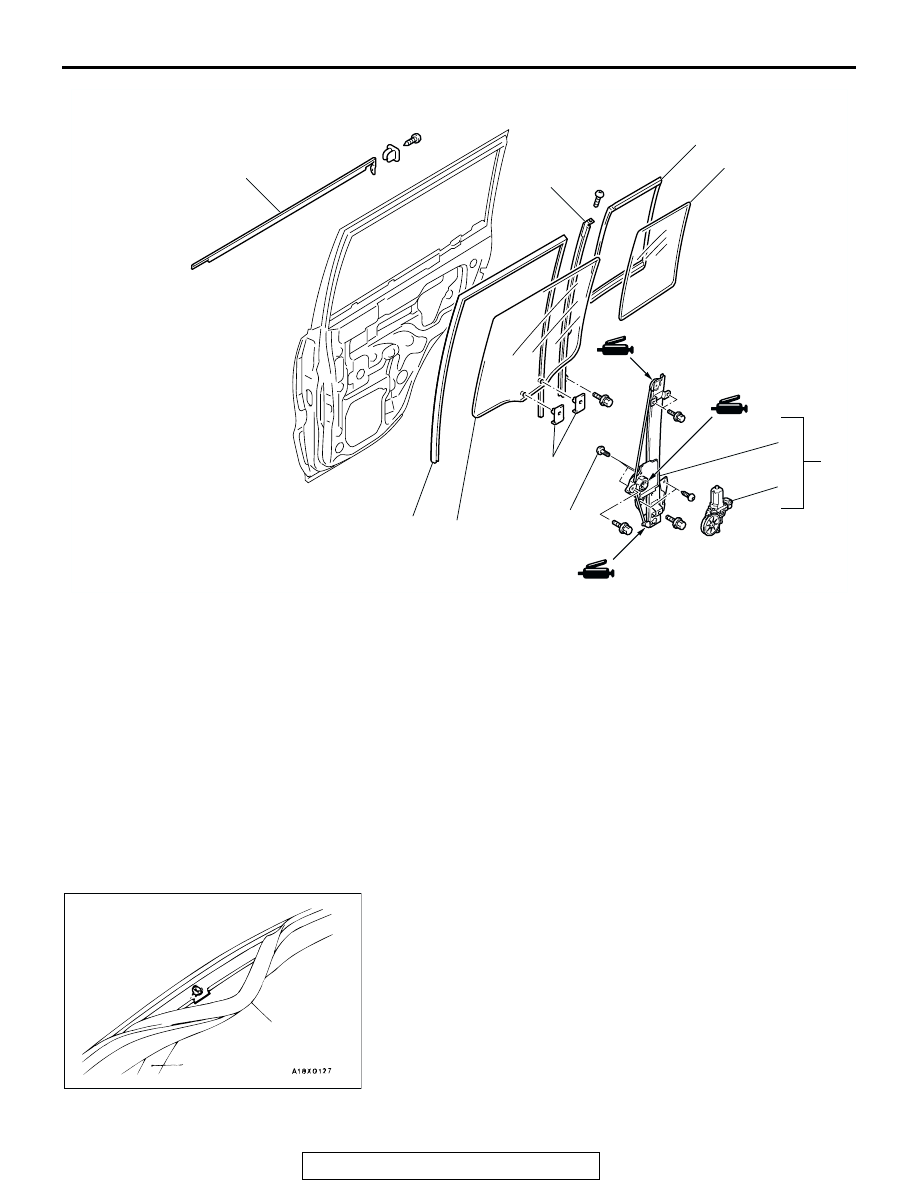
<<A>> DOOR CENTER SASH REMOVAL
1. Remove the door outer opening weatherstrip from the door 

center sash section only.

2. Remove the mounting screw for the door center sash, and 

remove the door center sash from the door panel.

AC308864

1

2

3

4

5

6

7

8

9

10

AB

5.4 ± 1.4 N·m
48 ± 13 in-lb

<REAR DOOR>

REMOVAL STEPS
1. DOOR BELTLINE MOLDING 

ASSEMBLY

2. DOOR WINDOW GLASS 

RUNCHANNEL

<<A>>

3. DOOR CENTER SASH
4. REAR DOOR WINDOW GLASS
5. DOOR GLASS HOLDER
6. POWER WINDOW REGULATOR 

AND MOTOR ASSEMBLY

7. POWER WINDOW MOTOR 

ASSEMBLY

8. POWER WINDOW REGULATOR 

ASSEMBLY

9. STATIONARY WINDOW GLASS
10. STATIONARY WINDOW 

WEATHERSTRIP

REMOVAL STEPS (Continued)

ACX00527

DOOR OUTER OPENING
 WEATHERSTRIP

CENTER SASH

AB

DOOR

TSB Revision

BODY

42-40

INSPECTION

M1421007600547

POWER WINDOW RELAY CONTINUITY CHECK

POWER WINDOW MOTOR CHECK

1. Connect a battery directly to the motor terminals and check 

that the motor runs smoothly.

2. Check that the motor runs in the opposite direction when the 

battery is connected with the polarity reversed.

3. If defect is found, replace the window regulator as an 

assembly. 

.

<Front door>

.

BATTERY 
CONNECTION

TESTER 
CONNECTION

SPECIFIED 
CONDITION

Not applied

− 5

Open circuit

• Connect terminal 1 

to the negative 
battery terminal

• Connect terminal 3 

to the positive 
battery terminal

− 5

Less than 2 ohms

1

2 3

4

5

1

3

4

5

ACX01544

ACX02285

AC000413

JUNCTION BLOCK (FRONT VIEW)

POWER WINDOW RELAY

AB

BATTERY CONNECTION

SLIDER POSITION

• Connect terminal No. 1 and 

the negative battery terminal.

• Connect terminal No. 2 and 

the positive battery terminal.

UP

• Connect terminal No. 2 and 

the negative battery terminal.

• Connect terminal No. 1 and 

the positive battery terminal.

DOWN

AC309019

1 2

DOOR

TSB Revision

BODY

42-41

<Rear door>

DOOR HANDLE AND LATCH

REMOVAL AND INSTALLATION

M1423004600243

BATTERY CONNECTION

SLIDER POSITION

• Connect terminal No. 1 and 

the negative battery terminal.

• Connect terminal No. 2 and 

the positive battery terminal.

UP

• Connect terminal No. 2 and 

the negative battery terminal.

• Connect terminal No. 1 and 

the positive battery terminal.

DOWN

AC309022

1 2

Pre-removal Operation
• Door Trim Removal (Refer to 

P.42-31

.)

Post-installation Operation
• Door Inside Handle Play Check (Refer to 

P.42-28

.)

• Door Outside Handle Play Check (Refer to 

P.42-28

.)

• Door Trim Installation (Refer to 

P.42-31

.)

• Door Fit Adjustment (Refer to 

P.42-26

.)

AC204109

5.9 ± 1.0 N·m
52 ± 9 in-lb 

5.9 ± 1.0 N·m
52 ± 9 in-lb 

1

2

3

4

5

6

7

5

6

7

2

1

AB

<FRONT DOOR>

<REAR DOOR>

DOOR HANDLE AND DOOR LATCH 
ASSEMBLY REMOVAL STEPS

>>C<<

1. DOOR INSIDE HANDLE
• WATERPROOF FILM (REFER TO 

P.42-31

.)

2. DOOR OUTSIDE HANDLE
3. DOOR LOCK KEY CYLINDER

>>B<<

4. REAR LOWER SASH

5. DOOR LATCH ASSEMBLY
6. LINK ASSEMBLY
 DOOR CHECK REMOVAL STEPS
• WATERPROOF FILM (REFER TO 

P.42-31

.)

>>A<<

7. DOOR CHECK

DOOR HANDLE AND DOOR LATCH 
ASSEMBLY REMOVAL STEPS 

DOOR

TSB Revision

BODY

42-42

INSTALLATION SERVICE POINT

.

>>A<< DOOR CHECK INSTALLATION
Install the door check so that the identification mark faces 
upwards.

.

>>B<< REAR LOWER SASH INSTALLATION
Securely insert the rear lower sash into the window rear sash.

.

>>C<< DOOR INSIDE HANDLE INSTALLATION
1. Install the inside lock cable to the door inside handle as 

follows:

(1) Install the inner cable end in the inside lock cable to the 

clip in the door inside handle.

(2) Turn the inside lock knob to the door lock position.
(3) Install the outer cable end to the door inside handle 

securely.

(4) Install the clip to the inner cable.

2. Install the inside handle rod to the door inside handle.
3. Install the door inside handle to the door.

ITEM

IDENTIFICATION MARK

Front Door

Left door

20L

Right door

20R

Rear Door

Left door

26L

Right door

26R

ACX00541

IDENTIFICATION
MARK

AB

ACX00542

INNER
CABLE

OUTER 
CABLE
CLIP

CLIP

INSIDE LOCK ROD

DOOR INSIDE HANDLE

AB


Content   ..  675  676  677  678   ..