Mitsubishi Montero (2004+). Manual - part 568


  Index      Mitsubishi     Mitsubishi Montero - service repair manual 2004 year


Search            


Content   ..  566  567  568  569   ..


Mitsubishi Montero (2004+). Manual - part 568


RV METER

TSB Revision

CHASSIS ELECTRICAL

54A-241

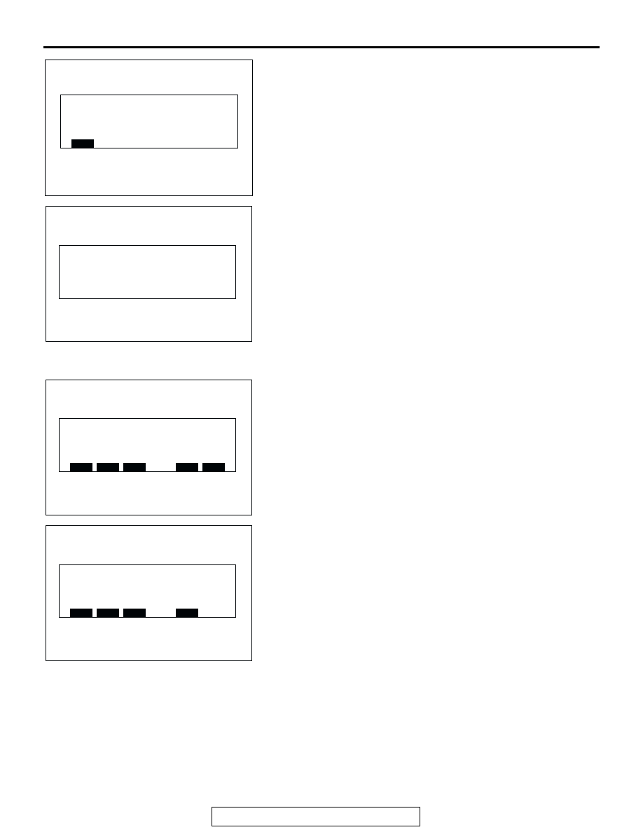
8. Press the function switch 1 [NEXT] on this screen. The 

vehicle signal status is displayed.

• ILL: ON or OFF

• Key position: "ACC" or "IG"

• Voltage: Battery voltage

• VSS: Vehicle speed

9. Press the function switch 1 [NEXT] on this screen. The 

message stating [Automatic diagnosis finished.] is displayed 
and within seven seconds later the screen moves to the 
screen just before the service mode screen.

.

Diagnosis mode
1. Press the "ADJ" switch with the ignition switch at "LOCK" 

(OFF) position, and while keeping on pressing, turn the 
ignition switch to the "ACC" or "ON" position. When the 
"ADJ" switch is pressed continuously for more than five 
seconds, the service function is activated at the same time 
with the reception signal (pip sound) and the first menu 
screen of the service mode is displayed.

2. Press the function switch 2 [DIAG]. The screen is switched 

to the diagnosis mode.

3. When respective function switches are pressed, the screen 

is switched as follows.

• When the function switch 1 [VER.] is pressed, versions of 

the monitor and the air-conditioner are displayed.

• When the function switch 2 [VEHICLE] is pressed, the sta-

tus of the vehicle signal is displayed.

• When the function switch 3 [COM.] is pressed, the commu-

nication and the connection are checked and the results are 
displayed.

• When the "ADJ" switch is pressed, the screen returns to the 

service mode second menu screen.

Signal check

ILL
Key position
Voltage
VSS

: OFF
: IG
: 99.9V
: 999km/h

ACX01991

NEXT

AB

Automatic diagnosis finished.

ACX01992

AB

Service mode

ACX01984

AUTO

DIAG.

HISTORY

NEXT

END

AE

SERVICE MODE FIRST MENU SCREEN

Diagnosis

ACX01993

VER.

VEHICLE

COM.

BACK

AB

RV METER

TSB Revision

CHASSIS ELECTRICAL

54A-242

4. Version display screen

Press the function switch1 [VER.]. In the case of 
No-automatic A/C circuit or automatic A/C circuit open, 
version is not displayed. Press "AD" J [BACK], returns to 
Diagnosis display.
NOTE: 

.

M: Mitsubishi Electric
D: Denso

5. Vehicle signal status display screen. Press the function 

switch 2 [VEHICLE]. Press "ADJ" [BACK], returns to 
Diagnosis display.

6. Press the function switch 3 [COM.]. When the ignition key is 

at "ACC" position, turn the ignition switch to "ON". Refer to 
"Automatic check mode". The check will be finished within 
10 seconds after ignition switch "ON" or pressing the 
function switch 3[COM.].

7. Communication and connection check results display 

screen

• When the function switch 2 is pressed on this screen, the 

unit status is displayed.

Version

Monitor
A/C

: M '99/SEP. Ver. xx.x
: D '99/SEP. Ver. xx.x

ACX01994

BACK

Signal check

ILL
Key position
Voltage
VSS

: OFF
: IG
: 99.9V
: 999km/h

ACX01995

BACK

AB

VEHICLE SIGNAL STATUS DISPLAY SCREEN

Checking the system connection.

ACX01986

Please Wait!

AB

Connection status

A/C  : Manual or less
Fuel : Full or Disconnected

ACX01996

EXIT

COMMUNICATION AND CONNECTION
CHECK RESULTS DISPLAY SCREEN

AB

Unit status

Monitor : OK
A/C

: E2

ACX01997

EXIT

AB

RV METER

TSB Revision

CHASSIS ELECTRICAL

54A-243

• When the function switch 2 is pressed on this screen, the 

inner status of the monitor is displayed.

• Press the function switch 3 on this screen, unit status dis-

played. The inner status of the monitor is displayed.

• Press the function switch" ADJ" [EXIT] to return to diagno-

sis menu.

• Press the function switch "ADJ" [BACK] to service mode 

first menu.

.

History mode
1. Press the "ADJ" switch with the ignition switch at "LOCK" 

(OFF) position, and while keeping on pressing, turn the 
ignition switch to the "ACC" or "ON" position. When the 
"ADJ" switch is pressed continuously for more than five 
seconds, the service function is activated at the same time 
with the reception signal (pip sound) and the first menu 
screen of the service mode is displayed.

2. Press the function switch 3 [HISTORY]. The screen is 

switched to the history mode.

3. Press the function switch 1 [CLEAR] on this screen,

The number of errors is erased; when the function switch 2 
is pressed, the screen is switched to the history mode 
second menu screen. When [EXIT] is pressed, the service 
mode display returns.

4. When the function switch 1 [CLEAR] is pressed on this 

screen, the number of errors is erased; when the function 
switch 2 is pressed, the screen switched to the history mode 
first menu screen. When [EXIT] is pressed, the service 
mode display returns.

.

Monitor status

Amb. Temp. : NG
Geomag. X: OK

Y: OK

Eng. ECU : OK
SWS
M-BUS

: OK
: OK

ACX01998

EXIT

AB

ITEM

DISPLAY 
EXAMPLE

CONTENTS OR 
CONDITION

Engine-ECU

(Powertrain control 
module)

SWS
M-BUS

000

Number of 
communication errors

ITEM

DISPLAY 
EXAMPLE

CONTENTS OR 
CONDITION

Amb. Temp
Geomag. X, Y

000

Number of 
connection errors

Service mode

ACX01984

AUTO

DIAG.

HISTORY

NEXT

END

AE

SERVICE MODE FIRST MENU SCREEN

Diag. history

Eng. ECU com. error
SWS         com. error

: 999
: 999
: 999

M-BUS      com. error

ACX01999

EXIT

CLEAR

AC

XXX

XXX

XXX

Diag. history

Amb. Temp.  error
Geomag.  X error

: 999
: 999
: 999

 Y error

ACX02000

EXIT

CLEAR

AB

HISTORY MODE SECOND SCREEN

RV METER

TSB Revision

CHASSIS ELECTRICAL

54A-244

Monitor check mode
1. Press the "ADJ" switch with the ignition switch at "LOCK" 

(OFF) position, and while keeping on pressing, turn the 
ignition switch to the "ACC" or "ON" position. When the 
"ADJ" switch is pressed continuously for more than five 
seconds, the service function is activated at the same time 
with the reception signal (pip sound) and the first menu 
screen of the service mode is displayed.

2. Press the "ADJ" [NEXT] switch.

The screen is switched to the service mode second menu 
screen.

3. Press the function switch 1 [MONITOR]. The screen is 

switched to the monitor check mode.

4. When respective function switches are pressed on this 

screen, the screen is switched as follows.

• When the function switch 1 [DISP.] is pressed, the screen is 

switched to the display check mode.

• When the function switch 2 [COMP.] is pressed, the screen 

changes to the geomagnetic sensor check mode.

• When the "ADJ" switch is pressed, the screen changes to 

the service mode second menu screen.

.

Display check mode
1. Press the "ADJ" switch with the ignition switch at "LOCK" 

(OFF) position, and while keeping on pressing, turn the 
ignition switch to the "ACC" or "ON" position. When the 
"ADJ" switch is pressed continuously for more than five 
seconds, the service function is activated at the same time 
with the reception signal (pip sound) and the first menu 
screen of the service mode is displayed.

Service mode

ACX01984

AUTO

DIAG.

HISTORY

NEXT

END

AE

SERVICE MODE FIRST MENU SCREEN

Service mode

ACX01985

MONITOR

BACK

END

AB

SERVICE MODE SECOND MENU SCREEN

Monitor check mode

ACX02001

BACK

DISP.

COMP.

AB

MONITOR CHECK MODE SCREEN

Service mode

ACX01984

AUTO

DIAG.

HISTORY

NEXT

END

AE

SERVICE MODE FIRST MENU SCREEN


Content   ..  566  567  568  569   ..